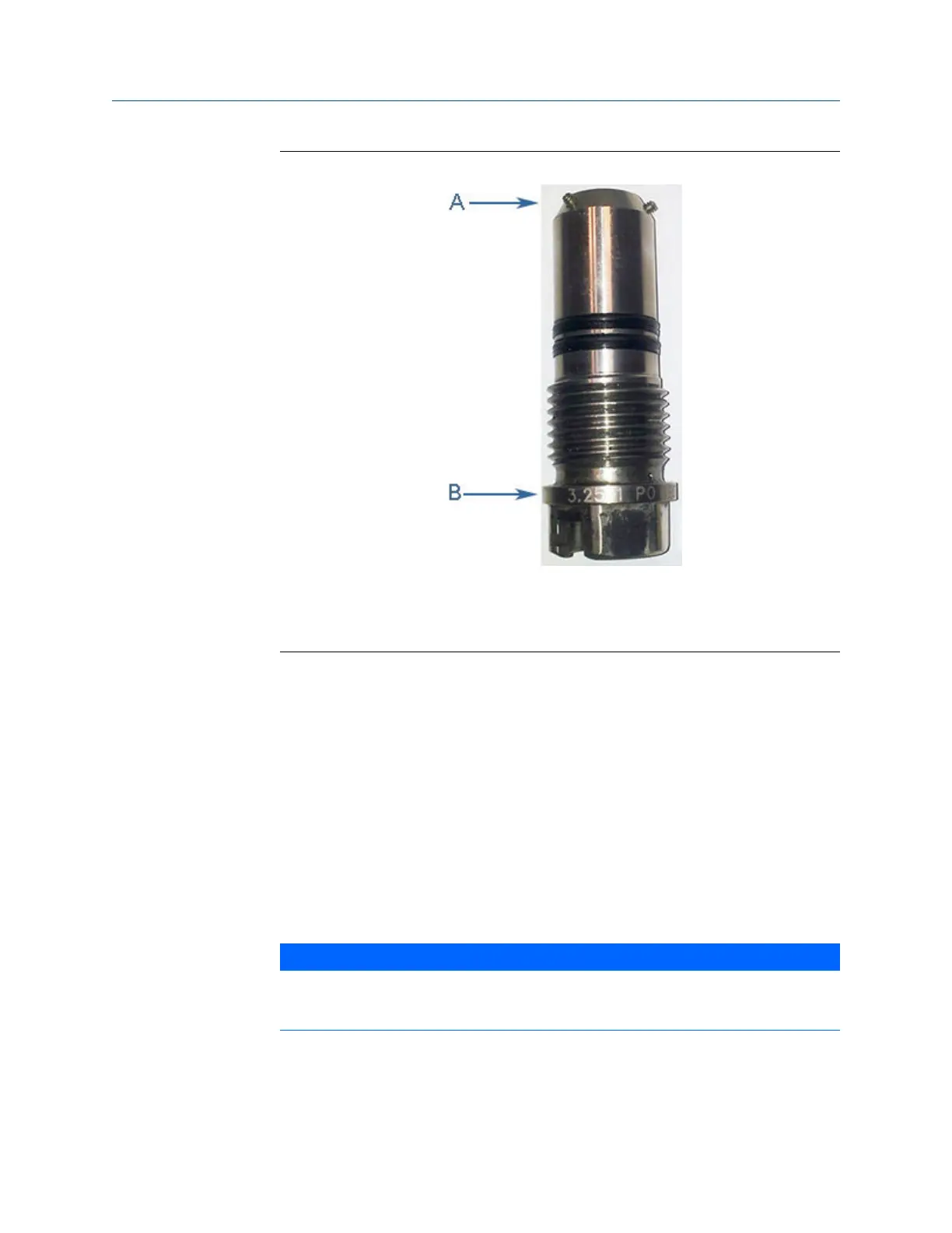
Transducer holder length and set screw identificationFigure 3-5:
A. Transducer holder set screws
B. Transducer holder length identification
7. Loosen the three Allen setscrews with a 1/16” hex driver securing the transducer
assembly and stalk, if installed. Carefully remove the transducer by pulling it from
the T-Slot transducer holder (or stalk if installed) without rotating.
8. Clean the holder with a dry cloth.
3.3.2 Install the transducer holder
1. Ensure that the Daniel 3410 Series Ultrasonic Gas Flow Meter transducer port,
mount, and T-Slot transducer holder assembly are clean and free of debris.
2. Insert the transducer (parts are keyed and can only be assembled one way) into the
stalk or into the new transducer holder if no stalk is required. Do not use any
lubricant on the O-rings or contacts of the transducers.
NOTICE
Ensure that the transducers identified as belonging to end 1 are installed on end 1 of the
meter housing and those identified as belonging to end 2 are installed on end 2 of the
meter housing.
Meter repairs
26 Gas Ultrasonic Flow Meter

 Loading...


