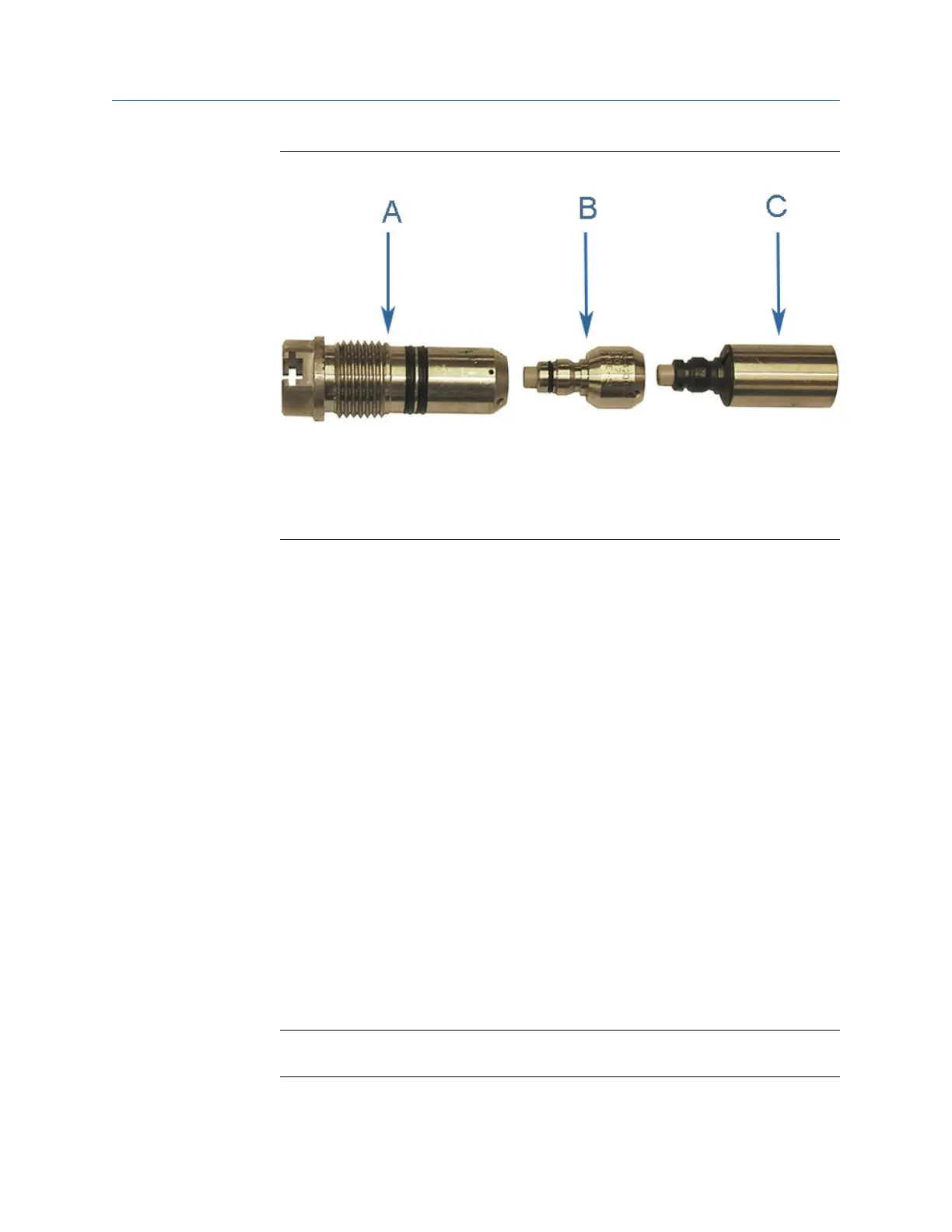
Transducer holder, stalk and transducer assemblyFigure 3-6:
A. Transducer holder
B. Stalk
C. Transducer assembly
3. Replace the O-rings and backup rings on the transducer holder. Make sure the
contoured side of the backup ring faces away from the transducer holder. It is highly
recommended that the O-rings be replaced when the transducer is removed from
the holder/stalk.
4. Use a 1/16” hex driver to equally tighten the three Allen set screws on the
transducer holder to secure the transducer assembly and the stalks (if installed).
5. Apply a light coat of Molykote 111
(1)
Silicone grease or equivalent to the transducer
holder O-rings.
6. Ensure that the transducer port, mount, and T-Slot transducer assembly are clean
and free of debris.
7. Apply a small amount of nickel anti-seize compound (P/N 2-9-9960-134) to the
outer threads of the transducer holder.
8. Insert the T-Slot transducer assembly into the meter transducer port. Tighten with
crescent wrench to securely seat the assembly in the mount. Do not over tighten.
9. Plug the transformer module into the transducer holder assembly. The transformer
module is keyed and can only be installed one way.
10. Place the transformer retainer over the transformer module. Ensure the transformer
retainer threads are aligned correctly and hand-tighten. Use an 1 1/8” wrench and
turn clockwise until fully seated in the transducer holder.
11. Align the keyed transducer cable and securely seat into the transducer holder and
secure with retaining clips.
Note
The transducer cable is keyed and will only go on one way.
(1) Molykote 111 is a trademark of Dow Corning Corporation, U.S.A.
Meter repairs
Maintenance and Troubleshooting manual 27

 Loading...


