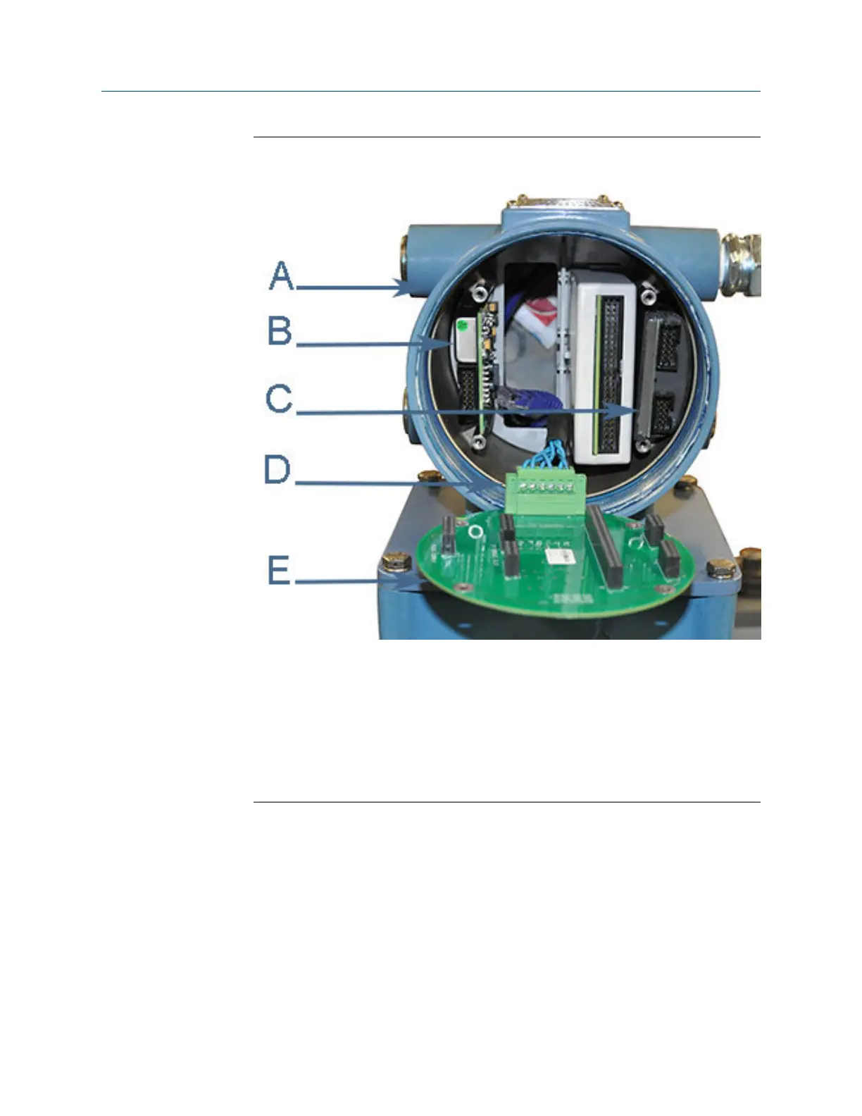
Power Supply board replacementFigure 3-16:
A. Non-terminal end of Transmitter Electronics Enclosure
B. Power Supply board
C. I.S. Barrier board (inside the Guide Plate)
D. Acquisition cable
E. Backplane board
5. Pull the Backplane board out of the enclosure. This disconnects the I.S. Barrier
Board. Lay the Backplane board down with the Acquisition Cable still attached (the
Power Supply board may remain attached to the Backplane when you remove it
from the enclosure).
6. Plug the new Power Supply board and the I.S. Barrier Board onto the Backplane
Board.
7. Insert the Backplane, I.S. Barrier board and the Power Supply Board into the
enclosure and fully seat the CPU Module and Optional I/O Module.
Meter repairs
42 Gas Ultrasonic Flow Meter

 Loading...


