1592015610 User manual IC200D EVO GB rel1.0 10.11.2015_rev10 IC200D 144/192
50. PARAMETERS LIST
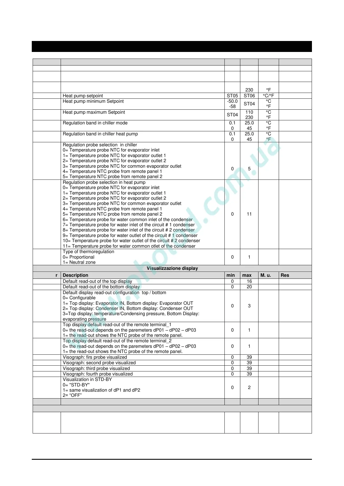
Heat pump minimum Setpoint
Heat pump maximum Setpoint
Regulation band in chiller mode
Regulation band in chiller heat pump
Regulation probe selection in chiller
0= Temperature probe NTC for evaporator inlet
1= Temperature probe NTC for evaporator outlet 1
2= Temperature probe NTC for evaporator outlet 2
3= Temperature probe NTC for common evaporator outlet
4= Temperature NTC probe from remote panel 1
5= Temperature NTC probe from remote panel 2
Regulation probe selection in heat pump
0= Temperature probe NTC for evaporator inlet
1= Temperature probe NTC for evaporator outlet 1
2= Temperature probe NTC for evaporator outlet 2
3= Temperature probe NTC for common evaporator outlet
4= Temperature NTC probe from remote panel 1
5= Temperature NTC probe from remote panel 2
6= Temperature probe for water common inlet of the condenser
7= Temperature probe for water inlet of the circuit # 1 condenser
8= Temperature probe for water inlet of the circuit # 2 condenser
9= Temperature probe for water outlet of the circuit # 1 condenser
10= Temperature probe for water outlet of the circuit # 2 condenser
11= Temperature probe for water common otlet of the condenser
Type of thermoregulation
0= Proportional
1= Neutral zone
Default read-out of the top display
Default read-out of the bottom display
Default display read-out configuration top / bottom
0= Configurable
1= Top display: Evaporator IN, Bottom display: Evaporator OUT
2= Top display: Condenser IN, Bottom display: Condenser OUT
3=Top display: temperature/Condensing pressure, Bottom Display:
evaporating pressure
Top display default read-out of the remote terminal_1
0= the read-out depends on the paremeters dP01 – dP02 – dP03
1= the read-out shows the NTC probe of the remote panel.
Top display default read-out of the remote terminal_2
0= the read-out depends on the paremeters dP01 – dP02 – dP03
1= the read-out shows the NTC probe of the remote panel.
Visograph: firs probe visualized
Visograph: second probe visualized
Visograph: third probe visualized
Visograph: fourth probe visualized
Visualization in STD-BY
0= "STD-BY"
1= same visualization of dP1 and dP2
2= “OFF”
Type of unit
0= Air / air Chiller
1= Air / water Chiller
2= Water / water Chiller
 Loading...


