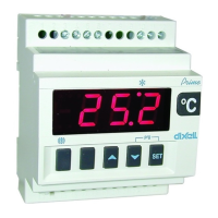
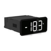
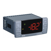
Instrument XRB shall be mounted on vertical
panel, in a 29x71 mm hole, and fixed using
the special bracket supplied. The
temperature range allowed for correct
operation is 0 to 60°C. Avoid places subject
to strong vibrations, corrosive gases,
excessive dirt or humidity. The same
recommendations apply to probes. Let air
circulate through the cooling holes.
Power Supply: 110VAC or 230VAC,
50-60Hz
oA1: always set as main compressor
output (CP1)
Power Supply: 110VAC or 230VAC,
50-60Hz
oA1: always set as main compressor
output (CP1)
Power Supply: 110VAC or 230VAC,
50-60Hz
oA1: always set as main compressor
output (CP1)

 Loading...
