9.6 Basic function and Air Leak Test
CAUTION: MOVING PARTS
Applying pressure to the actuator will cause the actuator/valve assembly to operate.
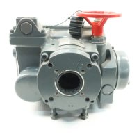
1. Apply pressure (max. 8 bar/120 psi) to ports A and B. Use some soap suds at the
indicated points: around pinion top (1), pinion bottom (2), the end caps (3) and
limit stops (4).
2. In case of leakage around:
a. The limit stop bolts: Turn the lock nut of the bolts tighter, until the leakage
stops.
b. The end caps: Disassemble the end caps, replace o-rings and reassemble.
c. The pinion top or bottom and A- or B- port: Disassemble the complete
actuator, replace o-rings and reassemble.
Figure 36 Basic function and air leak test
A
B
 Loading...