FB3000 RTU Instruction Manual
D301851X012
November 2023
Introduction 3
Operates in Class I Division 2 non-incendive and Ex ec Zone 2 non-sparking
environments when installed within a suitable enclosure.
Eight slot chassis may be extended with one, two, or three extension chassis.
Four-slot chassis available for smaller applications. It can also serve as the final
extension chassis (furthest on the right) in a multi-chassis assembly.
Supports I/O and communications modules (logic module holding I/O and
communications electronics/logic) and associated “personality” modules (handling
wiring and termination).
Eight-slot chassis supports one or two power supply modules (four-slot chassis
supports one).
Obtains power from a DC power supply (10.5-30Vdc).
Supports serial communication options for RS-232 and RS-485.
Provides two Ethernet (10/100/1000Base-T) ports.
Provides Micro A-B USB connector to support DNP3 communications.
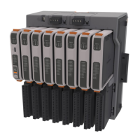
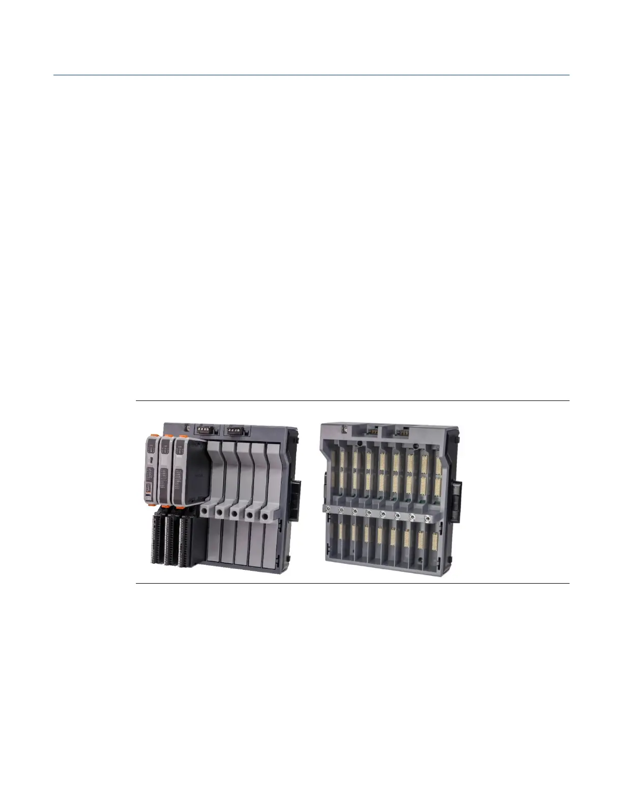
1.3 FB3000 RTU Chassis
The FB3000 RTU has either a four-slot or an eight-slot chassis. The CPU is always in slot
one of the base chassis.
Figure 1-2. Chassis – 8 Slot Version (with/without slot covers)
Each slot includes an upper section and a lower section. The upper section holds the
internal logic module, and the lower section holds the personality module used for wiring.
If your RTU is not fully populated with modules, you can fill the empty slots with slot
covers to protect the connectors from dust. These are installed/removed using the same
screws used for personality modules.
If you require more than seven I/O slots provided by an eight-slot chassis, you can
optionally purchase one, two, or three extension chassis to attach to the base chassis,
allowing an additional 8, 16, or 24 I/O slots for a total of 15, 23, or 31 slots in a single RTU.