FB3000 RTU Instruction Manual
D301851X012
November 2023
58 I/O Configuration and Wiring
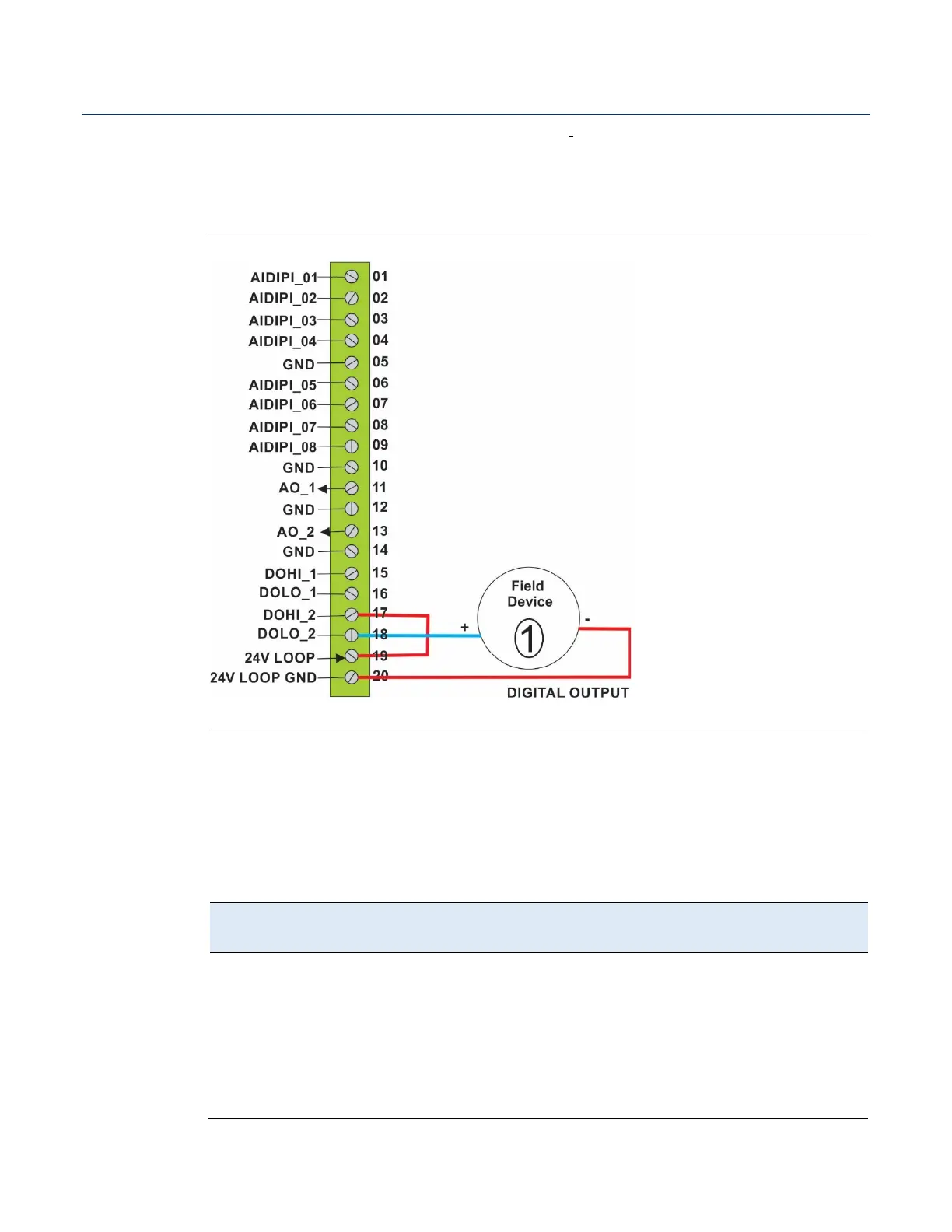
Figure 3-8 shows how to wire a digital output as a contact closure using the internal 24V
loop supply. The total current for all devices connected to a DO channel must not exceed
500 mA. For example, you could wire two devices in parallel, one with 200 mA, and
another with 300 mA. This figure shows a single device using 500 mA.
Figure 3--8. Digital Output (DO) Wiring – Contact Closure using 24V Loop Supply
500 mA load max field device
3.1.5 Pulse Inputs (3MIX12/3MSG12)
The 12-channel mixed I/O module includes eight channels you can individually configure
as either analog inputs (AI), digital inputs (DI) or pulse inputs (PI).
When configured as pulse inputs, the PI channels have the following characteristics:
Table 3-6. Pulse Input Characteristics
Supported
Input (PI)
through
AIDIPI_08 can be
individually
configured as
pulse inputs.
When a channel is configured as a PI it cannot be
used as a DI or AI channel.
The range of pulse inputs must remain within the
span of 0VDC to 30VDC.
All pulse inputs have 1V hysteresis applied to
them; switching levels are 2VDC for rising signals
and 1VDC for falling signals.