FB3000 RTU Instruction Manual
D301851X012
November 2023
26 Installation
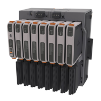
Power
Supply
Control
Power
Supply
Loop
Power*
Supply
Control
Power
Supply
Loop Power*
Module (3AODO8 and
3OTSG8)
Communications Module
(3SERL4, 3SRSG4,
COM04)
*Th
ese values represent total current draw from the external loop power supply. The loop
power current draw from any individual module must not exceed 200 mA.
Important
Total amperage for the FB3000 from control power cannot exceed 5A, and total
amperage for loop power cannot exceed 5A. Refer to Table 2-4 to view the amperage of
each module used in your planned installation. Based on the number of each type of
module used in your installation, determine the total control power amperage, and the
total loop power amperage used across all chassis. If the total amperage for either
control power or loop power exceeds 5A, you must either remove one or more modules
so the total falls below 5A, or if possible, replace a 12V power supply with a 24V power
supply so that you do not exceed the 5A limit
.
2.8.3 Power Fail and Shutdown Trip Points
If FB3000 power falls below certain levels (trip points), the RTU stops operating and shuts
down.
If power drops to the power fail trip point, the RTU firmware initiates an orderly
shutdown procedure. If power falls below that to the shutdown trip point, hardware
shuts down abruptly.
Note
Because of variation in power measurements, trip points shown in Table 2-5
are
approximate.
Table 2-5. Power Fail and Shutdown Trip Points (Approximate)
Power Fail Trip Point (Approx.)
Shutdown Trip Point (Approx.)