FB3000 RTU Instruction Manual
D301851X012
November 2023
70 I/O Configuration and Wiring
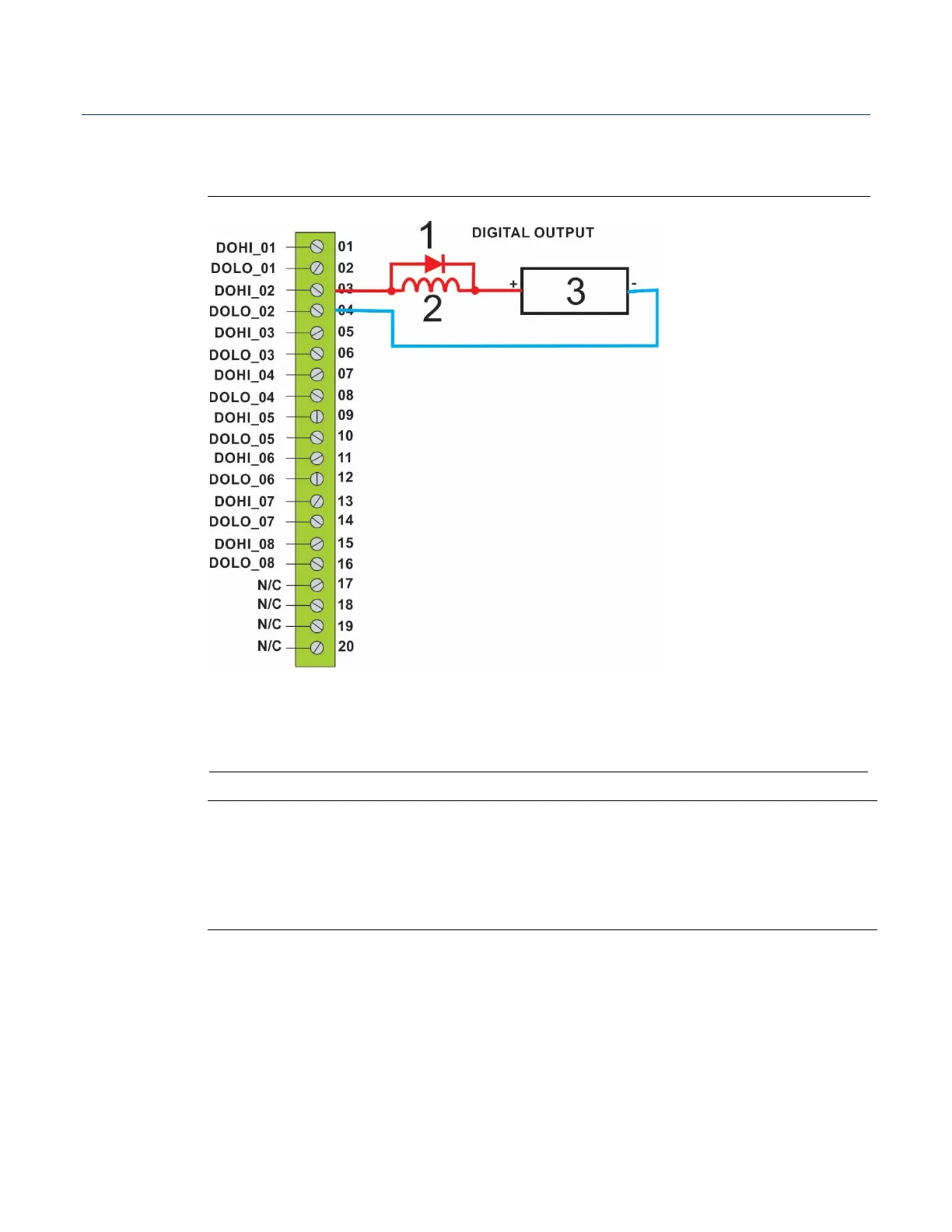
Figure 3-17 shows how to wire a digital output (DO_02) to drive an inductive load (such as
a relay coil).
Figure 3-17. Digital Output (DO) Wiring
Relay coil or inductive load
Note
When using a digital output to drive an inductive load (such as a relay coil), place a
suppression diode across the load. This protects the DO from the reverse Electro-Motive
Force (EMF) spike generated when the inductive load is switched off. (See DO2 in Figure 3-
17.)