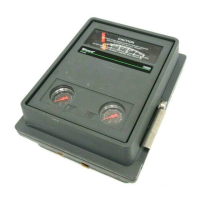
4195KA, KB, KC, and KS Controllers
Instruction Manual
Form 5207
April 2007
5-6
SET POINT
INDICATOR
PROCESS POINTER
REMOTE SET POINT
CONNECTED HERE
INPUT ELEMENT
CONNECTED HERE
CONNECTING
LINK
FLAPPER
NOZZLE
PROPORTIONAL
BELLOWS
(VENTED)
POSITIVE FEEDBACK
BELLOWS
PROPORTIONAL
BAND ADJUSTMENT
SUPPLY
PRESSURE
RELAY
OUTPUT PRESSURE
TO FINAL CONTROL
ELEMENT
REVERSE ACTION
QUADRANT
FLAPPER
PIVOT
FEEDBACK
LINK
FEEDBACK
MOTION
DIRECT ACTION
QUADRANT
INPUT MOTION
FLAPPER DETAIL
SUPPLY PRESSURE
OUTPUT PRESSURE
NOZZLE PRESSURE
POSITIVE FEEDBACK PRESSURE
B1546−2 / IL
Figure 5-4. 4195KS Series Controller Schematic
Figure 5-3 shows the relationship between the
percent of sensor range between switching points
and the proportional band setting on the controller.
The following example illustrates how to use figure
5-3.
Example: The sensing element has a range of 30
psi. The lower switching point is to be set at 10 psi
and the upper switching point is to be set at 25 psi.
Proceed as follows:
D Divide the differential gap (the difference
between the upper and lower switching points) by
the sensing element range. Multiply the result by
100 as shown in the following equation.
D Locate the 50 percent line on figure 5-3. Move
along this line until you intersect the curve. Read the
proportional band setting on the left hand axis. For
this example, the setting is approximately 35
percent.
Differential Gap
Sensing Element Range
x 100 =
15 psi
30 psi
x 100 = 50
1. Using the curve in figure 5-3, determine the
correct proportional band setting for the desired gap
(expressed as a percent of the maximum input
element span) between the switching points.
2. Set the proportional band knob to the desired
setting determined in step 1.
3. Adjust the set point to the desired lower switching
point.
4. Decrease the process pressure until the
controller output signal switches from zero pressure
to full supply pressure.
5. Increase the process pressure to the desired
switching point at which the controller output signal
switches from full supply pressure to zero pressure.
6. Narrow or widen the proportional band slowly
until the output signal switches from full supply
pressure to zero pressure.
7. Repeat steps 4 through 6 until the controller
output switches at the desired points.
8. Observe the process pointer when the output
switches at the upper switching point. The process
pointer indication should be within +/-2 percent of
the set point indication.

 Loading...


