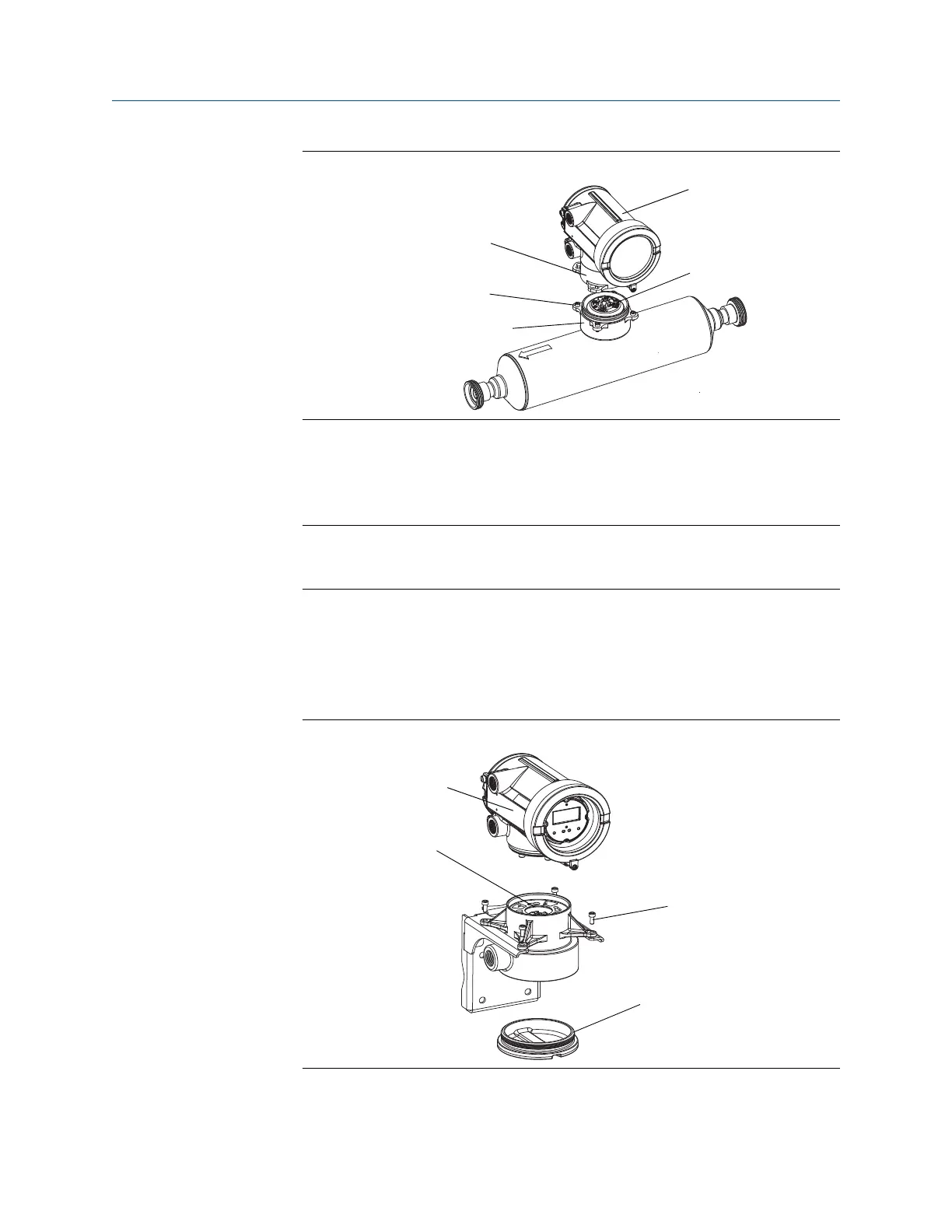
Integral installation componentsFigure 10-1:
Base
4 x cap screws (4 mm)
Transition ring
Transmitter
Core processor
b. Rotate the transmitter counter-clockwise so that the cap screws are in the
unlocked position.
c.
Gently lift the transmitter straight up, disengaging it from the cap screws.
Important
Do not disconnect or damage the wires that connect the transmitter to the core
processor.
d. Check the state of the core processor LED.
4.
If you have a 9-wire remote installation:
a. Remove the end-cap.
9-wire remote installation componentsFigure 10-2:
Transmitter
Core processor
4 x cap screws (4 mm)
End-cap
Troubleshooting
204 Micro Motion
®
Model 1700 Transmitters with Analog Outputs