— Provides clear access for installing cabling to the transmitter.
— Provides clear access to all wiring terminals for troubleshooting.
2.2 Additional considerations for retrofitting
existing installations
□ The transmitter installation may require 3 in (76 mm) to 6 in (152 mm) of additional
wiring for the input/output and power connections. This length would be in addition to
the currently installed wiring. Confirm you have the additional wiring necessary for the
new installation.
□ Before removing the existing transmitter, be sure to record the configuration data for
the currently installed transmitter. At initial startup of the newly installed transmitter,
you will be prompted to configure the meter via a guided setup.
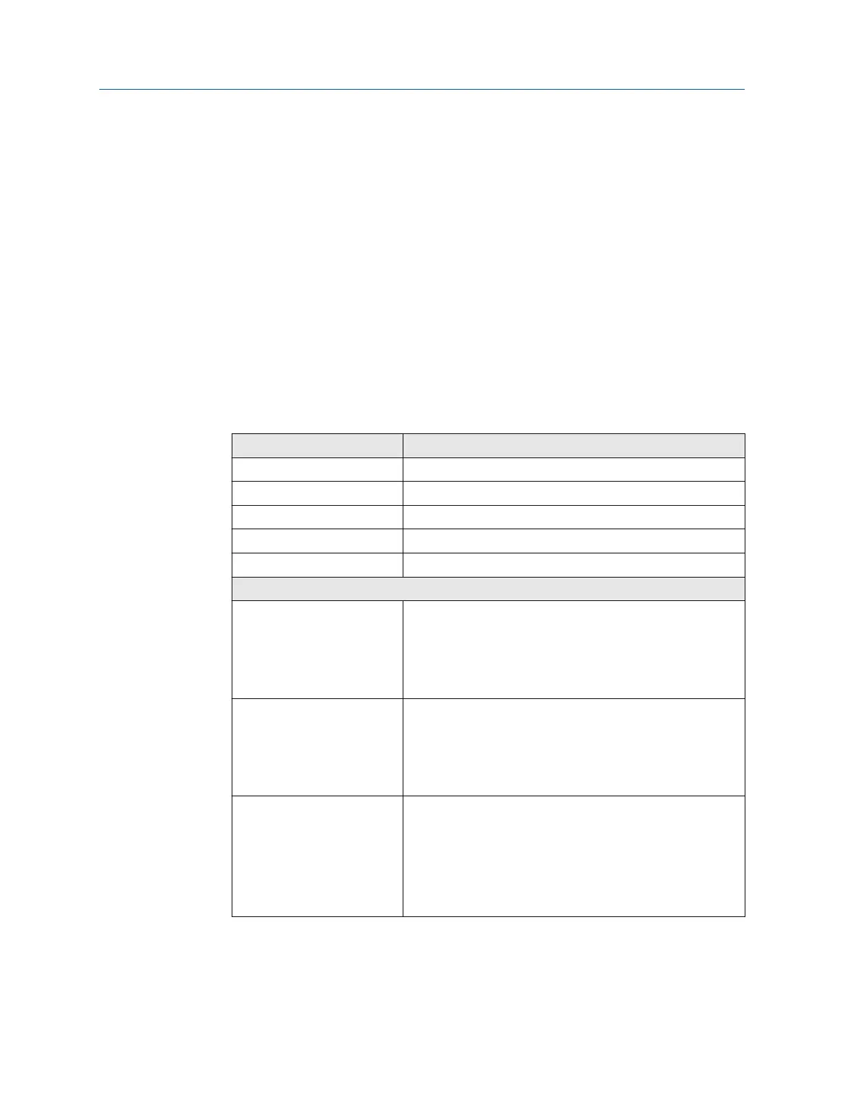
Record the following information (if applicable):
Variable Setting
Tag
Mass flow units
Volume flow units
Density units
Temperature units
Channel configuration
mA Outputs 1 — Power (Internal or External):
— Source:
— Scaling (LRV, URV):
— Fault Action:
mA Outputs 2 (optional) — Power (Internal or External):
— Source:
— Scaling (LRV, URV):
— Fault Action:
Frequency Outputs (optional) — Power (Internal or External):
— Source:
— Scaling (LRV, URV):
— Fault Action:
— Dual output:
Planning Installation Manual
February 2020 MMI-20027478
8 Micro Motion 5700 Transmitters with Configurable Outputs

 Loading...


