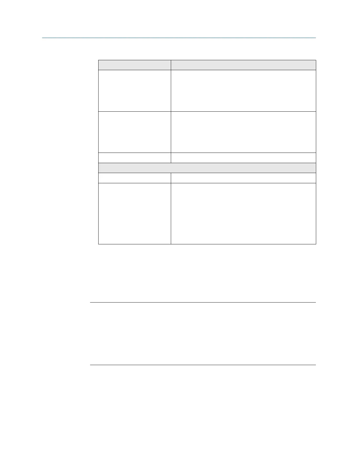
Variable Setting
Discrete Outputs (optional) — Power (Internal or External):
— Source:
— Scaling (LRV, URV):
— Fault Action:
Discrete Input (optional) — Power (Internal or External):
— Source:
— Scaling (LRV, URV):
— Fault Action:
RS-485 Address:
Calibration parameters (for 9-wire installations only)
Flow calibration factor FCF (Flow Cal or Flow Calibration Factor):
Density calibration factors — D1:
— D2:
— K1:
— K2:
— TC:
— FD:
2.3 Power requirements
Self-switching AC/DC input, automatically recognizes supply voltage:
• 85 to 240 VAC, 50/60 Hz, 6 watts typical, 11 watts maximum
• 18 to 100 VDC, 6 watts typical, 11 watts maximum
Note
For DC power:
• Power requirements assume a single transmitter per cable.
• At startup, the power source must provide a minimum of 1.5 amps of short-term
current per transmitter and not pull voltage below 18 VDC.
• Length and conductor diameter of the power cable must be sized to provide 18 VDC
minimum at the power terminals, at a load current of 0.7 amps.
Cable sizing formula
M = 18V + (R x L x 0.7A)
• M: minimum supply voltage
• R: cable resistance
• L: cable length (in Ω/ft)
Installation Manual
Planning
MMI-20027478 February 2020
Installation Manual 9

 Loading...


