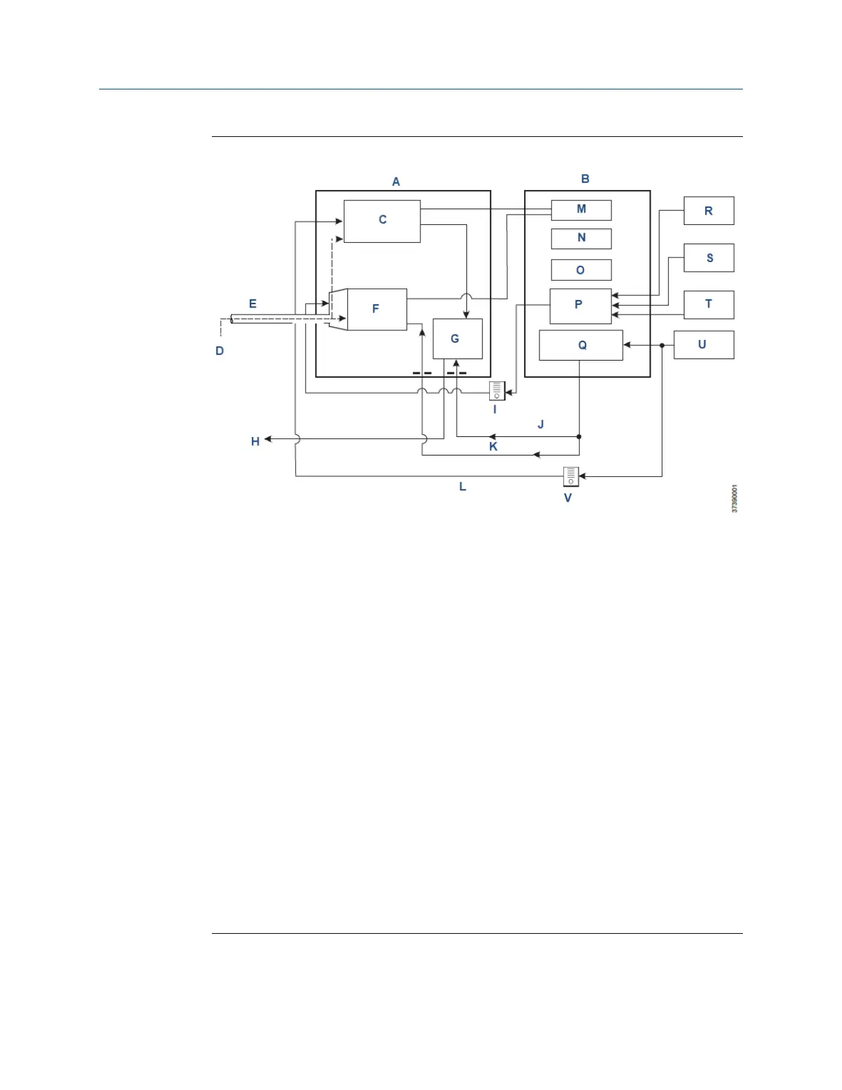
Figure 1-2: System Operation Diagram
A. Sensor housing
B. Electronics housing
C. COe combustibles sensor
D. Sample gas
E. Probe
F. O
2
sensor
G. Eductor
H. Exhaust
I. Flow meter 7 scfh
J. Eductor air
K. Reference air
L. Dilution air
M. CPU
N. HART
®
board
O. Power supply
P. Optional test gas solenoids
Q. Instrument air solenoid
R. Low O
2
test gas
S. High O
2
test gas
T. CO test gas
U. Instrument air
V. Flow meter 50 cc/min. (0.1 scfh)
Manual Description and specifications
00809-0500-4880 December 2022
Rosemount OCX8800A 15