2.3.10 Heater power connections
Use the blue, white, orange, black, red, and yellow stranded wires in the heater
power cable to connect power to the three heaters in the sensor housing.
Match the wire colors to the corresponding heater power terminal blocks in the
sensor and electronics housings as shown in Figure 2-7 and Table 2-5.
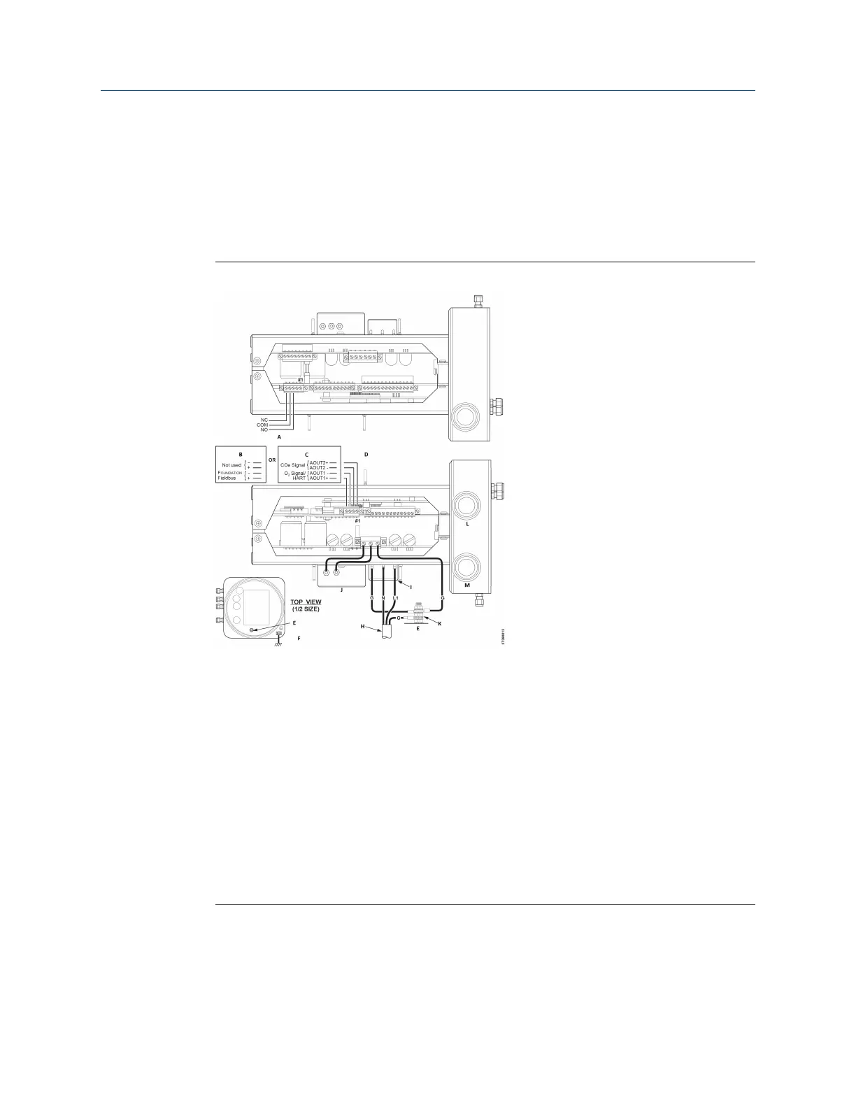
Figure 2-10: Line voltage, earth, and 4-20 mA connections
A. Alarm output relay terminal block
B. FOUNDATION
™
Fieldbus
C. HART
®
D. Signal output terminal block
E. Ground stud
F. Earth ground typical for electronics and sensor housing
G. Ground
H. Customer wiring
I. Terminal block
J. EMI filter
K. External tooth locks washer
L. Signal port ¾-in. NPT
M. Power port ¾-in. NPT
2.4 Pneumatic installation
Pneumatic system connections depend on whether reference air set, calibration
solenoids, and/or blowback equipment options are equipped on your transmitter.
Manual
Install
00809-0500-4880 December 2022
Rosemount OCX8800A 43