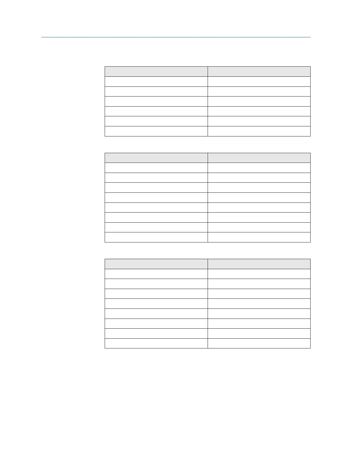
Table 10-2: J3 Connections
Wire color Connects to
Yellow 2 heater CO
Red 1 heater CO
Black 2 heater O
2
Orange 1 heater O
2
White 2 heater sample block (SB)
Blue 1 heater SB
Table 10-3: J4 Connections
Wire color Connects to
Yellow Exc+
Brown CO act+
Black CO act-
Red CO reference+
White CO reference-
Orange CJC+
Black CJC-
Black Exc-
Table 10-4: J5 Connections
Wire color Connects to
Red Thermocouple (T/C) CO+
Black T/C CO-
White T/C SB+
Black T/C SB-
Green T/C O
2
+
Black T/C O
2
-
Blue O
2
cell+
Black O
2
cell-
9. Disconnect the heater cable leads from the heater power connector (J3).
10. If moving the electronics housing to another work site, disconnect and
remove the power and signal cables and customer wiring conduits from the
housing.
11. Remove the remote electronics housing from its mounting and move it to a
suitable work area.
Maintenance and service Manual
December 2022 00809-0500-4880
248 Emerson.com/Rosemount