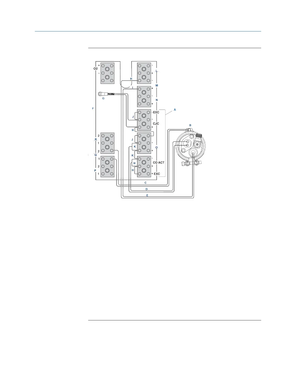
Figure 10-22: COe Sensor, Thermocouple, and Heater Connections
A. All wires at these terminals are in the CJC current loop.
B. COe sensor assembly
C. COe heater wires
D. COe sensor wires
E. COe thermocouple wires
F. Sensor housing terminals
G. CJC sensor
H. Red
I. Yellow
J. Blue
K. White
L. Thermocouple O
2
M. Thermocouple CO
N. Thermocouple sample block
O. CO reference
P. Heater sample block
Q. Heater CO
R. Heater O
2
11. Install and fasten the COe insulator (Figure 10-18) around the COe sensor
assembly.
All wiring must remain outside of the insulator.
Manual Maintenance and service
00809-0500-4880 December 2022
Rosemount OCX8800A 275