Safety
Information
Introduction
Product
information
System
design
Mechanical
installation
Electrical
installation
Getting
started
Optimisation
Parameters
Technical
data
Component
sizing
Diagnostics
156 Unidrive SP Regen Installation Guide
www.controltechniques.com Issue Number: 2
Modbus RTU protocol
Full details of the CT implementation of Modbus RTU are given in Chapter 7 Serial communications protocol in the Unidrive SP Advanced User
Guide.
The protocol provides the following facilities:
• Drive parameter access with basic Modbus RTU
• Drive parameter access via CMP extensions
• Option module internal parameter access via CMP extensions
• Access via an option module onto a network via CMP extensions (see specific Solutions Module User Guides for details)
• Drive parameter database upload via CMP extensions
• Drive Onboard PLC program upload/download via CMP extensions
• The protocol supports access to 32 bit floating point parameters
The following product specific limitations apply:
• Maximum slave response time when accessing the drive is 100ms
• Maximum slave response time when accessing option module internal parameters or via an option module to a network may be longer than
100ms (see specific Solutions Module specifications for details)
• Maximum number of 16 bit registers that can be written to, or read from, the drive itself is limited to 16
• Maximum number of 16 bit registers that can be written to, or read from, a Solutions Module or via a Solutions Module - see Solutions Module
User Guide
• The communications buffer can hold a maximum of 128bytes
Modbus RTU protocol, but with SM-Keypad Plus only
This setting is used for disabling comms access when the SM-Keypad Plus is used as a hardware key. See section 2.6.2 'Hardware key' feature in the
Unidrive SP Advanced User Guide for more information.
Used in all comms modes to define the baud rate.
*Modbus RTU only
This parameter can be changed via the drive keypad, via a Solutions Module or via the comms interface itself. If it is changed via the comms
interface, the response to the command uses the original baud rate. The master should wait at least 20ms before sending a new message using the
new baud rate.
There will always be a finite delay between the end of a message from the host (master) and the time at which the host is ready to receive the
response from the drive (slave). The drive does not respond until at least 1ms after the message has been received from the host allowing 1ms for the
host to change from transmit to receive mode. This delay can be extended using Pr 11.26 if required for both ANSI and Modbus RTU protocols.
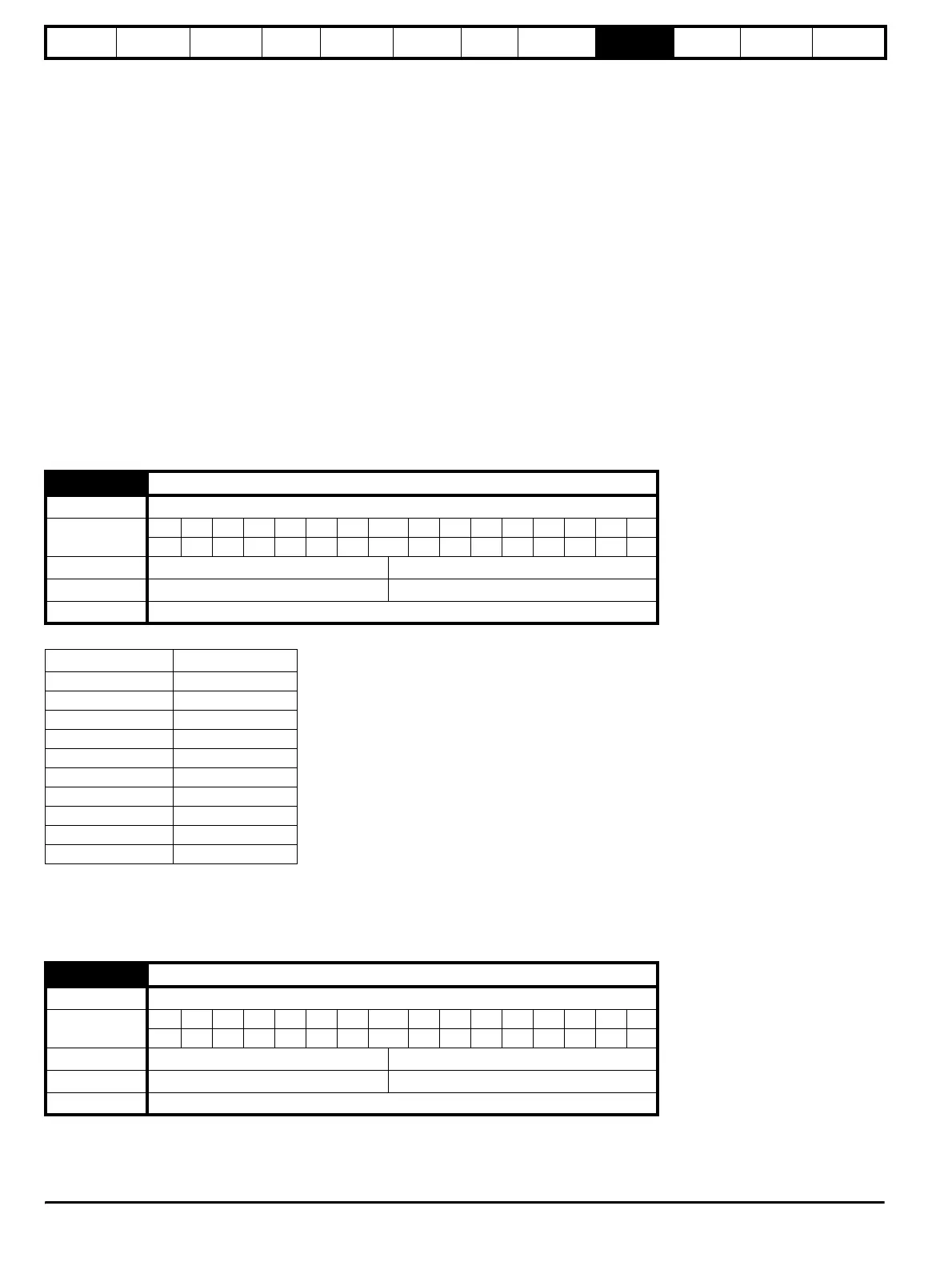
11.25 Baud rate
Drive mode Regen
Coding
Bit SP FI DE Txt VM DP ND RA NC NV PT US RW BU PS
1 111
Range Regen 0 to 9
Default Regen 6
Update rate Background
Parameter value String/baud rate
0 300
1 600
2 1200
3 2400
4 4800
5 9600
6 19200
7 38400
8* 57600
9* 115200
11.26 Minimum comms transmit delay
Drive mode Regen
Coding
Bit SP FI DE Txt VM DP ND RA NC NV PT US RW BU PS
111
Range Regen 0 to 250 ms
Default Regen 2
Update rate Background