Safety
Information
Introduction
Product
information
System
design
Mechanical
installation
Electrical
installation
Getting
started
Optimisation
Parameters
Technical
data
Component
sizing
Diagnostics
100 Unidrive SP Regen Installation Guide
www.controltechniques.com Issue Number: 2
Power feed-forward compensation can be used to reduce the transient DC bus voltage produced when a fast load transient occurs on drives
connected to the Regen drive. 100.0% power feed-forward is equivalent to an active current of Rated drive current / 0.45 (i.e. over current trip level)
and an AC terminal peak phase voltage equal to DC_VOLTAGE_MAX / 2. This scaling is the same as the power output from Pr 5.03 when high speed
output mode is used (see section 9.7 Menu 7: Analogue I/O ). Therefore an analogue output of the drive supplying the load and analogue input 2 or 3
of the drive acting as the supply Regen drive can be connected together to give power feed-forward compensation without further scaling if the two
drives are of equal rating. If the ratings are different the analogue input scaling must be used to give the correct power feed-forwards, where the
scaling is given by:
Load drive Rated drive current / Regen drive rated drive current
This parameter defines the strategy used for current trimming in regen mode. If Pr 3.11=0 then current trimming is only carried out once after power-
up. If Pr 3.11=1 current trimming is carried out after power-up and then before the drive runs each time it is enabled.
9.4 Menu 4: Current control
In Regen mode the drive operates in a reference frame that is aligned to the voltage at the drive terminals. Because the phase shift across the input
inductors is small, the reference frame is approximately aligned with the supply voltage. The maximum normal operating current is controlled by the
current limits.
DRIVE_CURRENT_MAX is used in calculating the maximum of some parameters and is fixed at 1.75 x rated drive current. The drive can operate up
to this level under normal conditions.
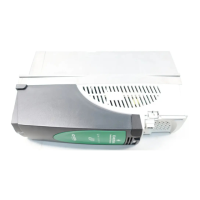
The relationship between the voltage and current for Regen mode operation is shown in the following vector diagram.
Definitions:
i
s
= Regen drive terminal voltage vector
vs = Regen drive current vector
CURRENT_LIMIT_MAX is used as the maximum for some parameters such as the user current limits. The maximum current limit is defined as
follows (with a maximum of 1000%):
Where:
Regen drive rated current is given by Pr 5.07
3.10
Power feed-forward compensation
Drive mode Regen
Coding
Bit SP FI DE Txt VM DP ND RA NC NV PT US RW BU PS
12 1 1
Range Regen ±100 %
Default Regen 0.00
Update rate 4ms
3.11
Current trimming mode
Drive mode Regen
Coding
Bit SP FI DE Txt VM DP ND RA NC NV PT US RW BU PS
111
Range Regen 0 to 1
Default Regen 0
Update rate 4ms read
Supply
voltage
vs
= Regen unit
terminal voltage
i
s
Regen mod
wLi
sy
CURRENT_LIMIT_MAX
Maximum current
Motor rated current
-------------------------------------------------------
100%×=