Safety
Information
Introduction
Product
information
System
design
Mechanical
installation
Electrical
installation
Getting
started
Optimisation Parameters
Technical
data
Component
sizing
Diagnostics
204 Unidrive SP Regen Installation Guide
www.controltechniques.com Issue Number: 2
11.2 Resistor sizing for multiple drive
systems
The charging resistor must be calculated for a multiple drive systems or
SPMD system due to the increased inrush current and where a Unidrive
SPMC cannot be used.
For applications where the total DC bus capacitance of the motoring
drives is greater than that of the Regen drive (one large drive supplying
several smaller drives). The following procedure and data should be
used to recalculate the resistor(s) required:
11.2.1 Procedure
1. Calculate the total DC bus capacitance of the system.
2. Calculate the energy stored in the systems DC bus capacitance at
the maximum supply voltage.
3. Calculate the minimum number of resistors required to meet this
energy value (round up to the nearest one), (Table 11-2).
4. Calculate the series parallel arrangement of resistors to produce the
total resistor value in the required range (Table 11-3 and Table 11-2).
Table 11-2 Charging resistors
DC bus capacitor energy is calculated from 0.5 x C
N
x 1.2 x V
2
BUS
.
Where C
N
is the nominal DC bus capacitance (Table 11-1) and the 1.2
factor allows for capacitance tolerance. V
BUS
is calculated from √2 x V
LL
(+10%) where V
LL
is the nominal line to line AC voltage.
Table 11-3 Softstart resistor
Example:
SPMD 1404 regenerating onto a 480Vac + 10% supply with SPMD 1404
motoring drive.
C
N
= 2 x 6600µF
= 13200µF
V
BUS
= √2 x 480 x 1.1
= 747V
Energy = 0.5 x 13200 x 10
-6
x 1.2 x (747)
2
= 4419J
Select resistor CT part number 1270-2483.
Number of resistors required =
Three resistors are therefore required which may be connected in
parallel.
11.3 Thermal / magnetic overload
protection for soft start circuit
Thermal / magnetic protection for the softstart resistor should be
provided to protect against a high / low impedance short circuit and the
risk of fire. A recommended device being a thermal magnetic overload.
The overload should be sized as following to provide thermal and
magnetic protection:
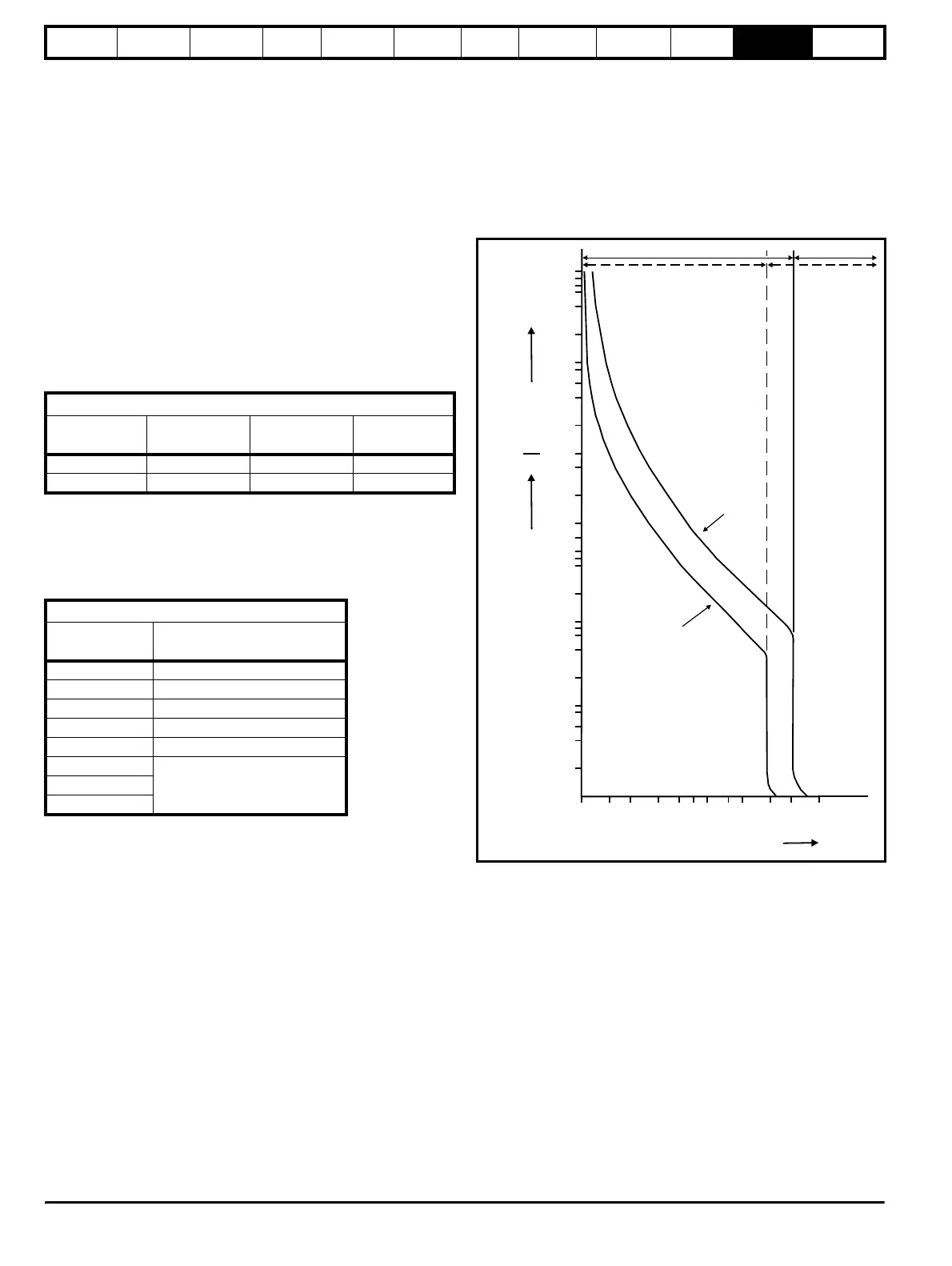
11.3.1 Thermal / magnetic overload characteristics
Figure 11-1 Example of tripping characteristic
11.3.2 Sizing of magnetic overload
The magnetic overload should be selected to the peak current and
charging time at power up with the trip being at for example 20 times the
nominal rated current of the overload. Therefore for a 20A peak current a
1A overload could be used.
The charging of a system takes a total of 5 time constants with this
having a decaying exponential current due to the RC network, therefore
at 5 time constants the system will have charged up with the current
being at approximately zero as shown in Figure 11-2.
The peak current and charge time during power up can be calculated
using the following formula.
Example: Peak current
480Vac supply +10%, total softstart resistance of 24Ω (2 x 48Ω in
parallel):
I
peak
= Vac (+10%) x 1.414 / Resistance
softstart
= (480 + 48) x 1.414 / 24 = 31.1A I
peak
Resistor data
Resistor value
Ω
Power rating
W
Energy rating
J
CT part
number
150 53 170 1270-3157
48 148 1,700 1270-2483
Softstart resistor range
Drive size Total softstart resistor value
Ω
1 12 to 252
2 5 to 158
3 3 to 83
4 2 to 50
5 1 to 34
6
1 to 24SPMA
SPMD
4419
1700
-------------
2.6=
0.01
0.02
0.04
0.06
0.1
0.2
0.4
0.6
1
2
4
6
10
20
40
1
2
4
6
10
20
40
60
120
1.5 2 3 41 56 810 15 20 30
14
21
10
r
pp
ng t
me
Seconds Minutes
Multiple of rated current
Thermal Trip
Area
Hot
Cold
Magnetic Trip
Area