1 – 9
VSS/VSM/VSH/VSSH • Installation, Operation and Maintenance Manual • Emerson • 35391SD
Symbol Identication
Use this list to identify symbols shown in the Piping & Identication Diagram.
3-Way Valve
S
3-Way Solenoid Valve
Angle Valve
Ball Valve
Basket Strainer
Block/Bleed Gauge Valve
Buttery Valve
Check Valve
Diaphragm Actuator
Diaphragm
Spring-Opposed
Diaphragm
Pressure-Balanced
Differential Pressure
Regulating Valve
Drive Coupling
Flange Set
FG
Flow/Sight Glass
Gate Valve
Globe Valve
Hand Expansion Valve
QE
Heater
Heat Trace
Insulation
MW
Man-Way Cover
Manifold Gauge Valve
M
Motorized Ball Valve
Needle Valve
Orice Plate
G
Pilot Light
Pipe Plug
Pipe Reducer
Pneumatic Actuator
Control Valve
Relief Valve
Regulating Valve Inlet
Pressure
Regulating Valve Outlet
Pressure
Rotary Valve
Rupture Disc
Schroder Valve
S
Solenoid Valve
Spring-Closing Drain
Valve
Stop/Check Valve
Strainer
T
Thermostatic Valve 3-Way
Thermowell (SW or NPT)
Thermowell (SW or NPT)
Venturi Injector Nozzle
Vibration Absorber
BY VILTER BY OTHERS
Scope of Supply
Section 1 • General Information
Air Drive
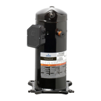
Compressor
Damper or
Louver
Engine Drive
Filter
Finned Tube
Heat Exchanger
Heat Exchanger
Motor
Shell and Tube
Heat Exchanger
Fan
Tank/Drum Vessel
Positive Displacement
Pump
Major Component Identication
Use this list to identify major components shown in the Piping & Identication Diagram.
 Loading...
