CG Drives & Automation 01-5958-01r0
5.2 Example - digital input
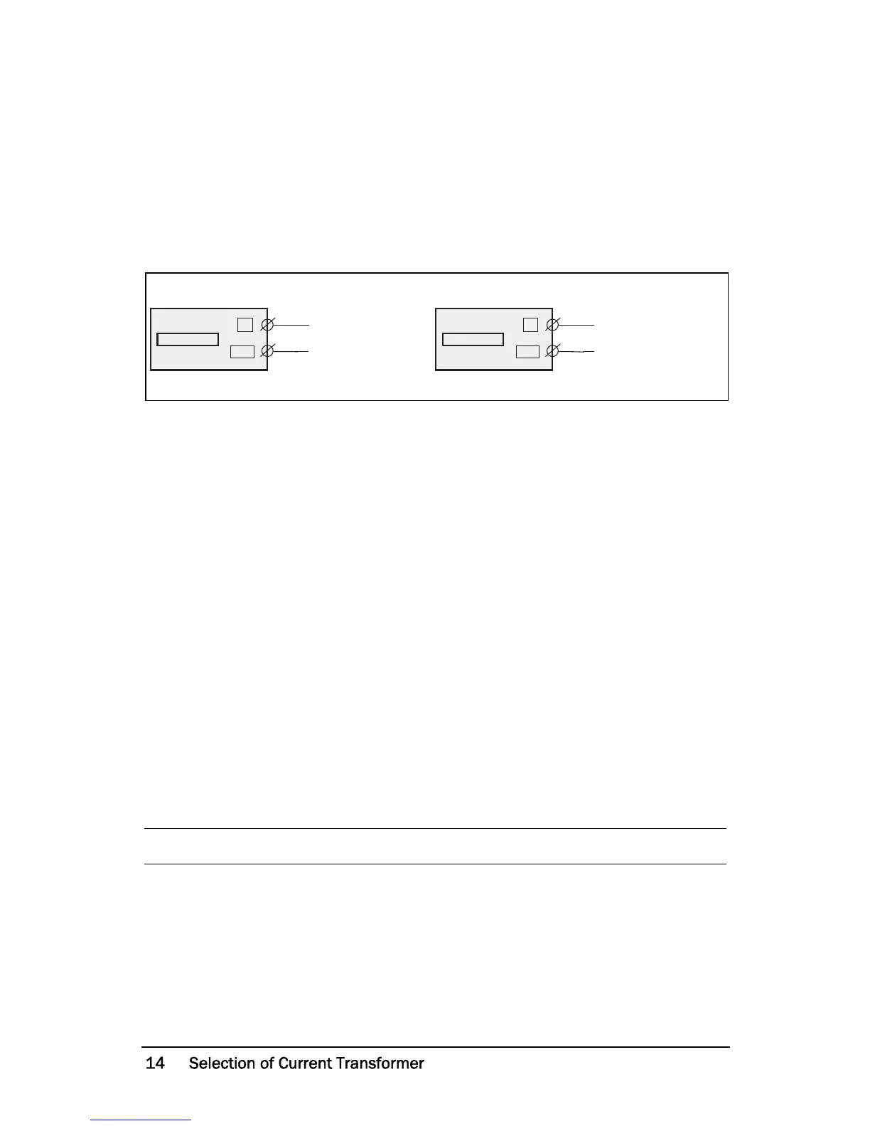
The digital input uses terminals 5 (DIG) and 6 (C - reference). Either a VAC or
a VDC signal may be used. Connect + to terminal 5 (DIG) and - to terminal 6
for VDC signal. Please note the polarity when DC voltage is used. See also
Fig1
and terminal 6: Max. 240 VAC (or 0 VDC-) and on terminal 5: N
(or 48 VDC+).
See also chapter 9, Advanced Features.
Fig. 3 Wiring example for digital input.
6 Selection of Current Transformer
6.1 Motors less than 100 A
1. Check the rated motor current on the motor plate.
2. Compare this value with the current in Table 1.
3. From Table 1, select the current transformer and the appropriate number of
windings.
Fig. 5 shows the different types of current transformer (CT) windings. In Fig.
5:1 the motor wire is just drawn through the CT, in the text and tables below
this is described as 1 (one) winding. Fig. 5:2 shows a CT with 2 windings and
Fig. 5:3, 3 windings. In other words the number windings is equal to the
number of times the motor wire “L1” is drawn through the hole of the current
transformer.
NOTE: Maximum length of the CTM cable is 1 m (39 inches).