9
7. 7. Liner HangerLiner Hanger
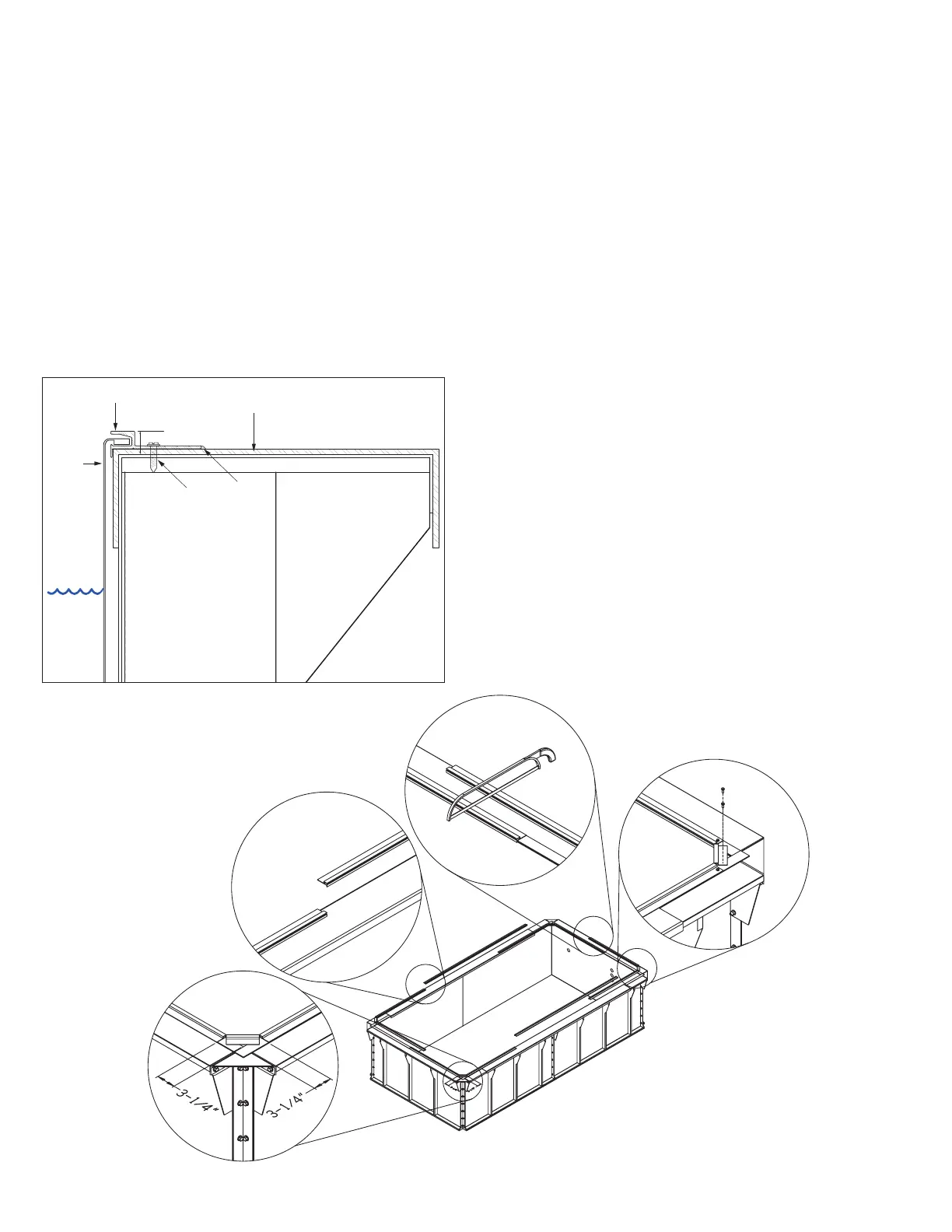
The standard Liner Hanger (A) installs around the perimeter
of the pool panel enclosure. The Pool Liner (B) hangs from
this extrusion using a bead that is heat welded onto the
top edge of the liner. Self-drilling fasteners (C) are included
in the Liner Hanger kit with a nut driver for your drill (Fig. 2).
Because the height of the Reinforcing Channels (D) that
fit over the top flange of the panel enclosure are slightly
higher than the surrounding top flange, PVC shims are
included to shim the hanger up to the level of the channels
to keep the whole system level. The shims can be cut with a
hacksaw or scored with a utility knife and snapped to fit the
size of the pool. Over the channels, the fasteners should be
drilled through the channel and the top flange. You may use
a pilot hole if you wish. Elsewhere, the fasteners must be
drilled through the shims and the top flange.
A
D
C
B
1/2"
(13mm)
E
Fig. 2
1. Bend the four 8’ (2,44m) lengths of Liner Hanger that
have been notched, so that they will fit into each
corner. Measure to ensure the middle corner piece
(between the notches) is centered in the corner (Fig. 3).
2. Use two self-drilling fasteners and PVC shims to secure
the small corner length first, by drilling through the
back corner of the Liner Hanger flange (Fig. 3).
3. Use a hacksaw to cut the notched corner sections if
they overlap in the center of the end panels, making
sure the gap at the joint is no greater than 1/8” (3mm).
Then secure the hanger sections to the end and side
panels, placing shims underneath the hanger anywhere
along the top flange that isn’t covered by a Reinforcing
Channel. The hanger sections should be flush with the
inside of the Reinforcing Channel and will protrude into
the pool the thickness of the channel everywhere else.
Fasteners should be spaced approximately 18” (46cm)
along the end and side walls (Fig. 3).
4. Install the remaining lengths of Liner Hanger to fill
the gaps between the notched corner sections. These
pieces vary in length, depending upon your pool size,
so may need to be trimmed at any point where two
sections overlap. The gap at any joint between two
sections should be no greater than 1/8” (3mm) (Fig. 3).
5. Silicone the gap (E), shown in Fig. 2, between the
Liner Hanger and the panel to ensure that no water
collecting on the top flange of the pool panel can work
its way down behind the liner. With the same objective
in mind, later silicone the joint between the top of the
liner hanger and the coping that you plan to install
over the entire top flange of the pool (if the optional
Apex Coping was not ordered).
1
2
4
Fig. 3