12
Shoes should be removed for the liner installation and
all future work in the pool to avoid damaging the liner.
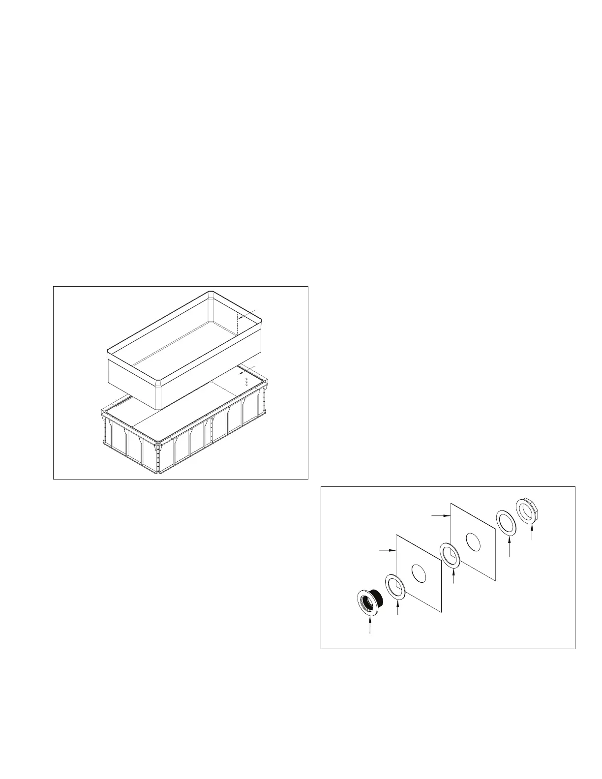
Spread the liner in the pool enclosure. Locate the vertical
seam (A) in the liner and center it at the front of the pool
(B). Place the four bottom corners of the liner in the four
corners of the pool (Fig. 8)
Install the liner by starting at the center of the front panel.
Fit the top bead of the liner into the slot in the Liner
Hanger, making sure the seam is centered on the front wall.
Hang the liner on the front wall, leaving the corners out.
Work your way around the perimeter of the pool, fitting
the bead evenly into the hanger. Again, do not install the
corners. While hanging the liner, continuously verify the
alignment of the vertical seam, making sure it’s centered
on the front wall. If offset, shift the liner so that the seam
is centered on the wall. Install the liner bead in the corners
last. Fit the bead in both corners of one end first and then
install the liner in the corners on the opposite end. Smooth
the liner on the floor, pushing any wrinkles toward the
walls. Inspect the liner by running a finger along all of the
liner seams making sure there are no imperfections.
A
B
Fig. 8
Turn the vacuum on. When the liner is drawn back, check
to see that the corners are positioned properly. If not, turn
the vacuum off and shift the liner. Install the 12” (30cm)
sections of liner bead lock in each corner to lock the corners
in. With the vacuum running, smooth out all of the wrinkles.
When satisfied with the liner fit, start to fill with water.
Keep the vacuum running until there is about 3” (7,6cm)
of water in the shallowest portion of the pool. Turn the
vacuum off and remove all tape and the vacuum hose. Keep
filling until there is 6” (15cm) in the shallowest portion of
the pool. Do not fill beyond 6” (15cm) at this time.
Included in the box with the liner are No Diving signs.
Please post these in prominent locations around the pool.
The Endless™ pool is shallow and must never be used for
diving. Diving into the pool is a very serious hazard and
these stickers are intended to warn children of the risks.
Adult supervision is also critical whenever children use the
pool.
13. 13. Thru-Wall Connections (Part 1)Thru-Wall Connections (Part 1)
This section should only be followed if the optional
Hydraulic Treadmill or Hydrotherapy Jets were ordered.
IMPORTANT NOTES:
• When cutting holes in the liner, it is important that
the water level is approximately 3” (7,6cm) below
the hole that is being cut. An alternate method is to
position your knee in the corner of the liner, closest
to the hole you are cutting, to simulate the weight of
the water on the liner. Hold your knee in the corner
while cutting the round hole in the liner. Continue to
hold your knee in the corner until the thru-wall fitting
is installed through the pool wall. An additional per-
son is needed on the backside of the pool wall. This
technique should be used when it is not possible to
wait for the water to fill to approximately 3” (7,6cm)
below the hole being cut or if the liner does not
press firmly against the corner of the pool.
• If the optional Hydraulic Treadmill is being installed
in an Endless™ Elite Pool or in front of the left
Hydrodrive housing of an Endless™ Dual Propulsion
Pool, the holes for the Treadmill will be cut once the
water level is within 3” (7,6cm) of the lowest tread-
mill hole. The holes are higher up on the pool wall for
these models.
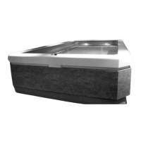
OPTIONAL HYDRAULIC TREADMILL
The Treadmill Thru-Wall Fittings need to be installed at this
time. Use a sharp utility knife to cut the round holes in the
liner (A), using the holes in the pool wall (B) as a template.
Disassemble the Thru-Wall Fitting. Insert the Fitting (C)
through the wall making sure the Black Gaskets (D) are
installed between the fitting and the liner, and the liner
and pool wall. Install the Cork Gasket (E) on the back of
the fitting before threading on the Lock Nut (F) (Fig. 9).
A
C
D
D
E
F
B
Fig. 9