21
21. 21. Electrical Wiring - 60Hz Electrical Wiring - 60Hz (U.S. and countries with a similar power supply)(U.S. and countries with a similar power supply)
ALL ELECTRICAL CONNECTIONS SHOULD BE MADE BY A LICENSED ELECTRICIAN.
NOTE: The following instructions are intended for Single Phase equipment. If Three Phase equipment was ordered,
refer to the Three Phase Equipment Supplemental Guide at this time.
ELECTRICAL REQUIREMENTS
MODEL HP
ELECTRICAL
REQUIREMENTS
MINIMUM
WIRE SIZE
RESULTS
ORIGINAL 5 HP (1) 220V 30A GFCI W/NEUTRAL 10 AWG
If wired as recommended, the
Water Quality System (WQS)
shares power with the Hydraulic
Power Unit for the Hydrodrive™.
When the Hydrodrive™ is turned
ON, the WQS & optional Jets are
off. The LED Lights & Keypad are
not affected.
The optional Treadmill operates
independently.
PERFORMANCE 5 HP (1) 220V 30A GFCI W/NEUTRAL 10 AWG
ELITE 7.5 HP (1) 220V 50A GFCI W/NEUTRAL 6 AWG
DUAL PROPULSION 5 HP (2) 220V 30A GFCI W/NEUTRAL 10 AWG
OPTIONAL TREADMILL 5 HP (1) 220V 30A GFCI W/NEUTRAL 10 AWG
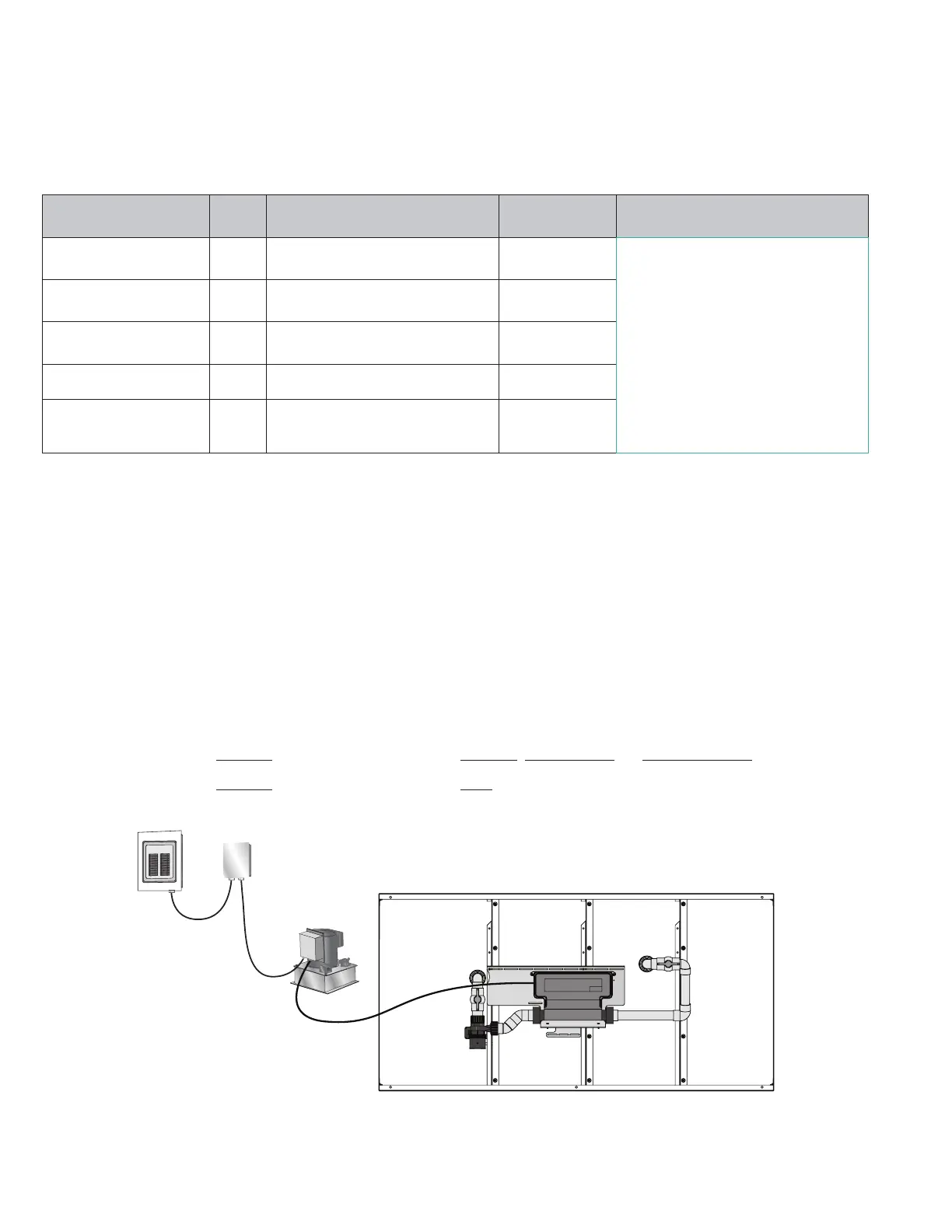
HYDRAULIC POWER UNIT & HEATER-CONTROLLER WIRING
A Ground Fault Circuit Interrupter (GFCI) is required for this product. A GFCI is a device that shuts off an electrical circuit
when it detects that electricity is flowing along an unintended path. The path could be through a person or water. The
purpose of this device is to reduce the chance of electrical shock.
An electrical shut off (A) MUST be installed between the Main Breaker Panel (B) and within 5’ (1,5m) of the intended
location of the Hydraulic Power Unit (C). Connect the pre-attached electrical whip (D), located on the left side of the
Hydraulic Power Unit Controller, to the power supply. The white wire (Neutral) MUST be connected to the load neutral
terminal of the GFCI breaker. An additional electrical whip (E) containing 4 wires is provided to supply power from the
Hydraulic Power Unit Controller to the Water Quality System Heater-Controller (F) as shown in Figure 42. When wired as
recommended, the system will redistribute power as needed so that the Water Quality System and Hydrodrive™ System
will not consume more amperage than the breaker will allow. Refer to the appropriate wiring instructions for the Endless™
Pool that was purchased:
Refer to the wiring on Page 22 if installing the Endless™ Original, Performance, or Dual Propulsion Pool.
Refer to the wiring on Page 23 if installing the Endless™ Elite Pool.
A
D
C
E
F
Fig. 42