13
OPTIONAL HYDROTHERAPY JETS: FACEPLATES
AND SUCTION COVERS
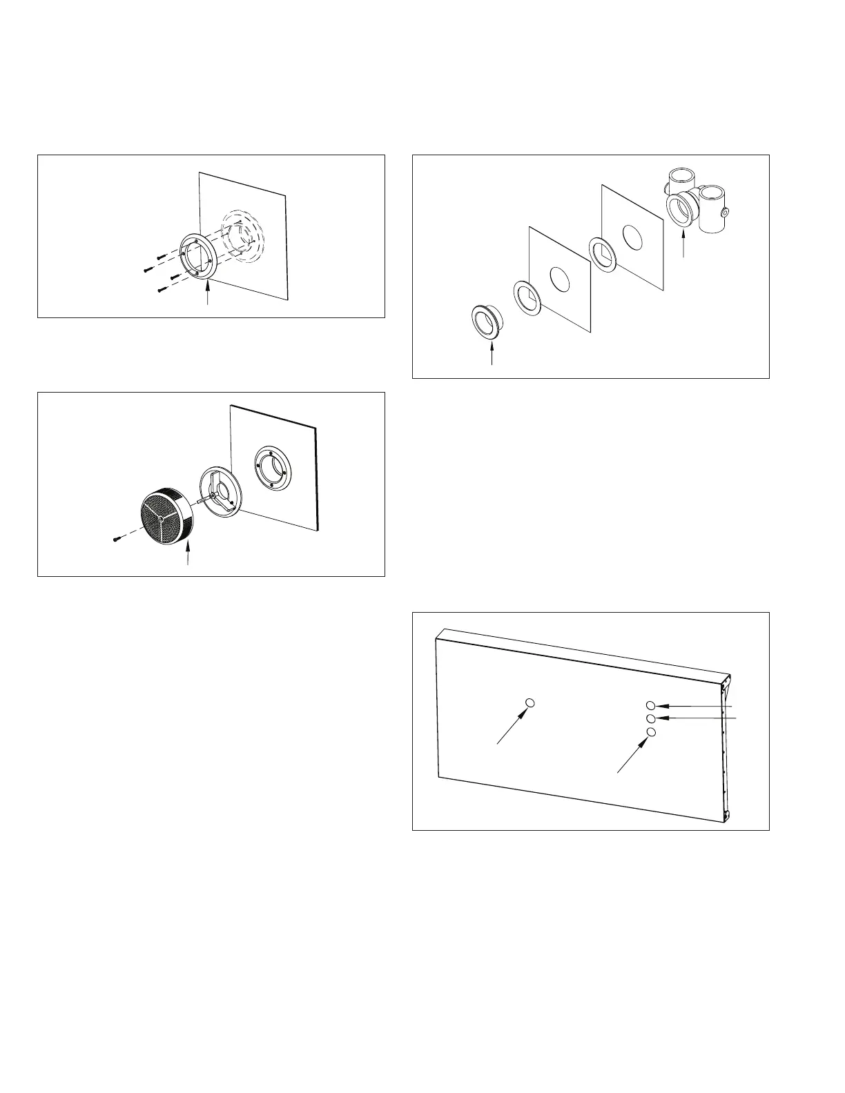
The Faceplates (A) for the Jet Suctions should now be
installed and holes for the Thru-Wall fittings can be
cut in the liner (Fig. 10). Refer to the Hydrotherapy Jets
Supplemental Guide for detailed instructions.
Fig. 10
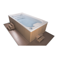
Next, install the VGB Suction Cover Assemblies (A) (Fig. 11).
Refer to the Hydrotherapy Jets Supplemental Guide.
Fig. 11
14. 14. Hydrodrive Component AssemblyHydrodrive Component Assembly
Provided with this Installation Manual is the appropriate
Supplemental Guide for the internal Hydrodrive
components. Refer to Hydrodrive Component Assembly
Supplemental Guide at this time to install the internal pool
components.
15. 15. Thru-Wall Connections (Part 2)Thru-Wall Connections (Part 2)
IMPORTANT NOTE: When cutting holes in the liner, it
is important that the water level is approximately 3”
(7,6cm) below the hole that is being cut. An alternate
method is to position your knee in the corner of the
liner, closest to the hole you are cutting, to simulate the
weight of the water on the liner. Hold your knee in the
corner while cutting the round hole in the liner. Continue
to hold your knee in the corner until the thru-wall fitting
is installed through the pool wall. An additional person is
needed on the backside of the pool wall. This technique
should be used when it is not possible to wait for the
water to fill to approximately 3” (7,6cm) below the hole
being cut or if the liner does not press firmly against the
corner of the pool.
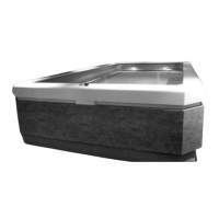
OPTIONAL HYDROTHERAPY JETS: JET
BULKHEAD FITTINGS AND JET BODIES
The four holes for the Jet Bulkheads can be cut in the
liner and the Jet Bulkhead Fittings (A) and Jet Bodies (B)
can be installed (Fig. 12). Refer to the Hydrotherapy Jets
Supplemental Guide for detailed instructions.
Fig. 12
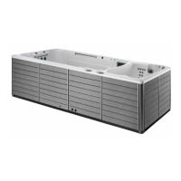
WATER QUALITY SYSTEM & HYDRAULIC HOSES
At this point, the holes for the Water Quality System
Suction (A), Water Quality System Return (B), and Hydraulic
Hoses (C) can be cut in the liner (Fig. 13).
NOTE: If installing an Endless™ Elite or Dual Propulsion
Pool, then there will be two sets (four total) hydraulic
hoses.
Use a sharp utility knife to cut the round holes in the liner,
using the holes in the pool wall as a template.
A
C
B
Fig. 13