16
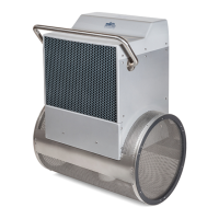
The next step is best accomplished with a helper. Align
the Heater-Controller (A) with the Pre-Plumbed Pump to
Heater Assembly (B). Make sure a T-Gasket (C) is installed
between the Heater-Controller and the pre-plumbed
assembly prior to tightening the Heater-Controller Union
(D). The raised section of the T-Gasket must sit in the
groove of the Tailpiece on the end of the pre-plumbed
assembly (Fig. 23).
A
B
C
D
Fig. 23
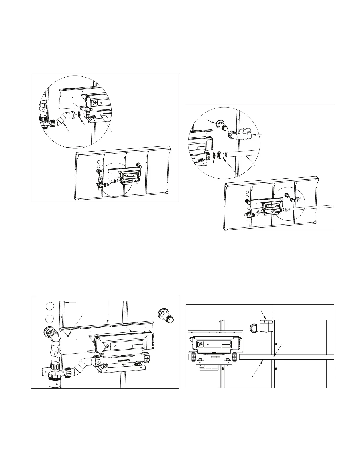
Once the Heater-Controller is attached to the plumbing,
make sure that it is level. Attach the Mounting Board (A) to
the pool panel Z-Brace(s) (B) with the provided self-drilling
screws (C).
Use a minimum of two screws. When the Mounting Board
lands on more than one Z-Brace, attach with two screws
along the top, through the slotted holes in the board. In the
instances when it lands on only one Z-Brace, attach with
one screw on the top and one screw on the bottom, through
the slotted holes in the board (Fig. 24).
B
C
Fig. 24
NOTE: If an Endless™ Dual Propulsion Pool is being
installed, an additional Heater-Controller is included for
additional heating efficiency. Refer to the Additional
Heater-Controller Supplemental Guide at this time.
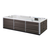
Attach the Pre-Plumbed Return Union and Valve Assembly
(A) to the Water Quality System Return Thru-Wall
Assembly (B). Make sure to wrap Teflon tape around the
threads of the adapter that is glued in to the Thru-Wall
prior to attaching the pre-plumbed assembly (Fig. 25).
Glue the Heater-Controller Tailpiece (C) onto the length of
Flex Pipe (D). Make sure to apply PVC primer and cement
to the faces of the glue joints. Attach this assembly to
the outlet of the Heater-Controller. Make sure there is a
T-Gasket (E) installed between the Heater-Controller and
Tailpiece prior to tightening the Heater-Controller Union
(Fig. 25).
A
B
C
E
D
Fig. 25
The next step is marking and cutting the Flex Pipe that
was attached in the previous step. Position a straight
edge tool (long level) against the end of the Ball Valve (A)
and extend it down onto the Flex Pipe (B) below it. Use a
marker to mark a cut line (C) on the pipe. The cut line must
be vertically aligned with the end of the Ball Valve (Fig. 26).
Remove the Flex Pipe from the Heater-Controller and cut
the pipe along the cut line.
C
B
Fig. 26
 Loading...