24
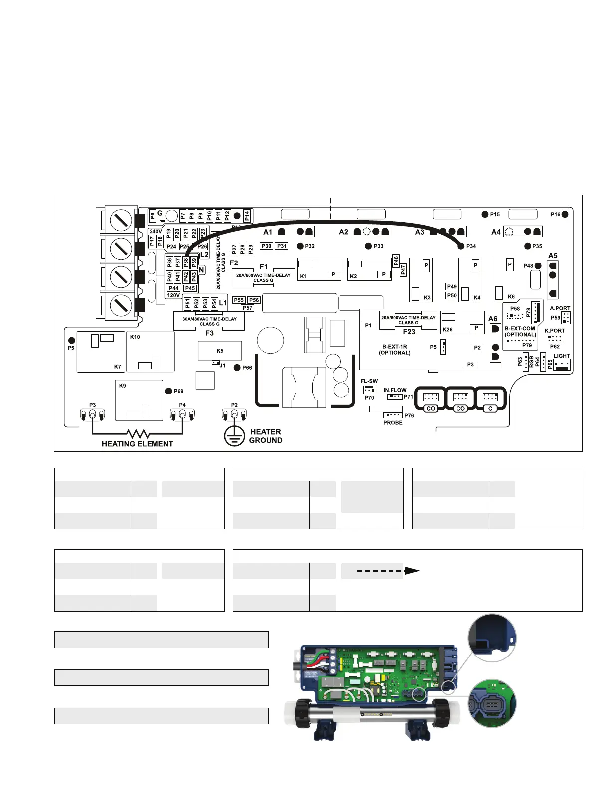
HEATER-CONTROLLER ACCESSORY WIRING
Each high voltage accessory wired into the Heater-Controller has an electrical cord with connectors that correspond with
the quick connect terminals OR the AMP connectors inside the Heater-Controller. Route the cords from the accessories
to the controller. The cords for the Keypad, LED Lights, and optional Remote Pool Monitoring should be routed through
the strain relief channel at the bottom of the controller. Refer to the printed circuit of the controller and the appropriate
accessory table below to determine the location of each connection.
NOTE: If BOTH the Circulation Pump and optional UV/EZ50 have an AMP connector on the end of the cord, BOTH the
Circulation Pump and UV/EZ50 plug into the A1 AMP connection via the splitter cable provided with the optional UV/
EZ50. Plug the splitter into the A1 connector. Then, plug the Circulation Pump and UV/EZ50 into the ends of the splitter.
NOTE: If the Gas Heater has been ordered, the P34 Gas Heater Jumper MUST be removed from P21 and connected to
P38. FAILURE TO COMPLETE THIS STEP WILL RESULT IN IMMEDIATE DAMAGE TO THE HEATER.
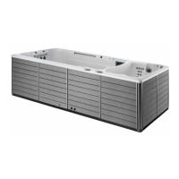
Strain relief
channel
C Connector
Green Wire/Ground P6 A1
Black Wire
Quick Connect Terminals AMP Connector
K1-P
White Wire P24
OPTIONAL UV/EZ50
Green Wire/Ground P7 A1 (splitter required
if circulation pump
has amp connector)
Black Wire
Quick Connect Terminals AMP Connector
P31
White Wire P25
OPTIONAL SKIRTING CORNER LIGHTS
Black Wire P46
Black Wire
Quick Connect Terminals
P36
OPTIONAL GAS HEATER
Green Wire/Ground P9 A3
Black Wire
Quick Connect Terminals AMP Connector
*P34 GAS HEATER JUMPER MUST
BE REMOVED FROM P21 AND
CONNECTED TO P38
K4-P
White Wire P39
OPTIONAL HYDROTHERAPY JETS
Green Wire/Ground P8 A2
Black Wire
Quick Connect Terminals AMP Connector
K3-P
White Wire P26
OPTIONAL REMOTE POOL MONITORING
(IN.TOUCH)
CO Connector
LED WALL/OPTIONAL LED BENCH LIGHTS
P65 Light Connector
(IN.XTEND)
C Connector
P34 GAS HEATER JUMPER