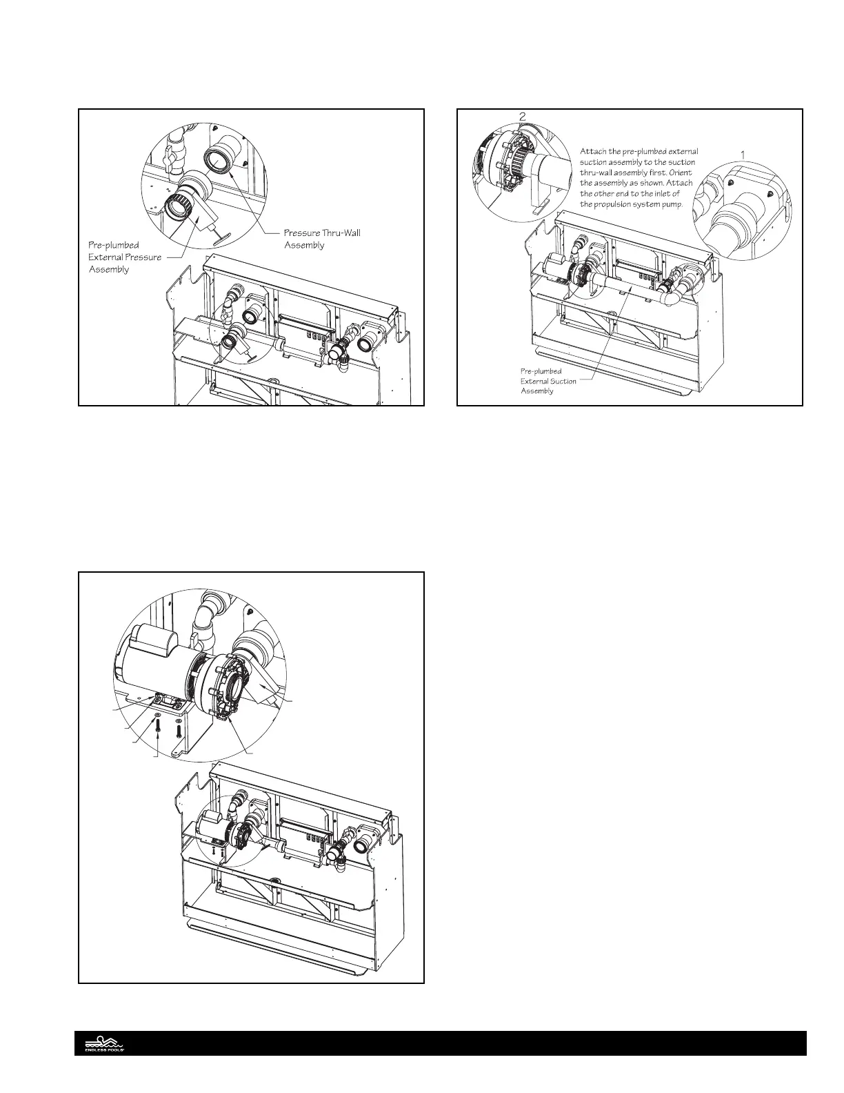
Propulsion System Plumbing
Attach the pre-plumbed external pressure assembly to the pres-
sure thru-wall assembly. Orient the assembly so the slide valve is
positioned as shown. Fig. 44
Fig. 44
Position the propulsion system pump on the pump support and
attach the pre-plumbed external pressure assembly to the outlet
of the pump. Fig. 45. Align the holes in the foot of the pump
with the holes in the pump support. Domestic (60Hz) pumps
will use the inside holes and Internatinal (50Hz) pumps will use
the outside holes. Secure the pump with the provided hex head
bolts, washers, and nuts located in the pump attachment hard-
ware bag.
Washer
Hex Head
Bolt
Propulsion System Pump
Pre-plumbed
External Pressure
Assembly
Washer
Nut
Fig. 45
Attach the pre-plumbed external suction assembly to the suction
thru-wall assembly. Orient the assembly so that the slide valve is
facing down. Attach the other end of the assembly to the inlet of
the propulsion system pump. Fig. 46.
Fig. 46
Bonding
All of the electrical equipment supplied is UL or CSA approved
and must be installed in accordance with local electric codes by
a licensed electrician. Bonding and grounding is an important
part of the process. All electrical components have bonding lugs
and should be bonded together and to the steel pool enclosure.
A bonding conductor shall be solid copper not smaller than 8
AWG and may be insulated, covered, or bare. If new construction
is involved where reinforcing rods are installed in the concrete,
this should be included in the bonding circuit. Each piece of
equipment should be separately bonded.
A #8 AWG bare copper wire and bonding kit is provided to
bond each piece of equipment. Attach lengths of bonding wire
to the bonding lugs located on each pump (circulation pump and
propulsion system pump) and connect the bonding wires to the
bonding bar located at the base of the heater-controller. Included
in the bonding kit is a bonding lug, machine screw, nut, and drill
bit. Attach the bonding lug to one of Z braces (vertical braces of
the front panel) above the heater controller. Feed the bonding
wire through the bonding lug and then connect the wire to the
bonding bar on the heater-controller.
20