Pool Start up
Open both water quality system ball valves making sure they
are parallel with the plumbing. Open both propulsion system
slide valves.
When power is rst introduced to the system, the heater-con-
troller will go through a boot-up cycle (which can last 2-5 min-
utes. e pump that drives the propulsion system will turn on for
about one minute during this cycle. At the end of the boot-up
cycle, the keypad should display the temperature of the water.
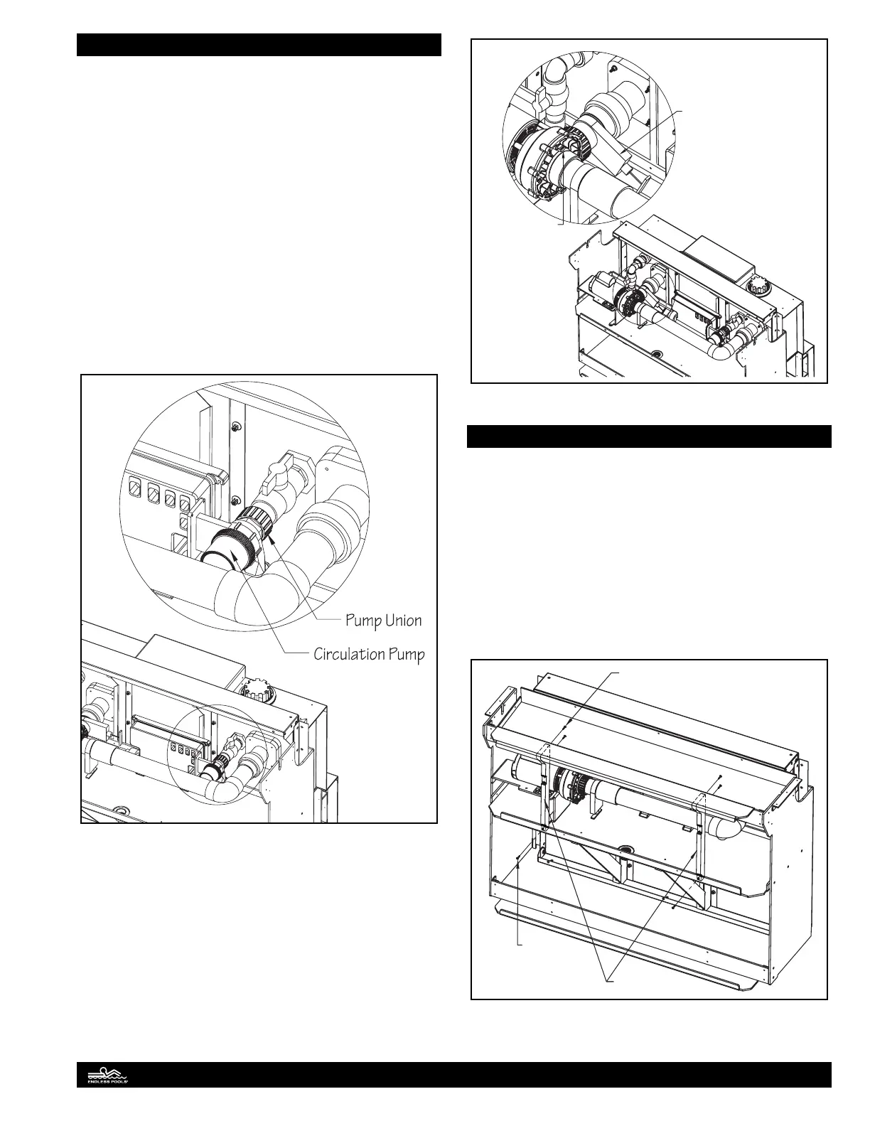
If the keypad is ashing “FLO” then air may need to be bled out
of the water quality plumbing. Turn the power to the pool o.
With a towel on hand, slowly unthread the union that’s attached
to the inlet of the circulation pump (small black pump) to allow
any air to escape the plumbing. Fig. 96. DO NOT completely
unthread the union. After the air has escaped, tighten the union.
Re-supply power to the pool. After the system goes through its
boot-up cycle, the water temperature should be displayed on the
keypad.
Fig. 96
To test the propulsion system, press the #1 key on the keypad. If
a swim current is not produced in the pool, air may need to be
bled out of the propulsion system piping. Press the #1 key until
the pump turns o. Close the slide valve at the outlet of propul-
sion system pump by removing the plastic clip and pushing in
the handle. After the valve is closed allow 1-2 minutes for water
to ll the plumbing lines and pump housing. Loosen the air plug
located in the 12 o’clock position on the pump housing to allow
air to escape. Once the air has escaped, tighten the plug and open
the slide valve. Turn the pump on high speed by pressing the #1
key twice. Fig. 97.
1
2
Close slide valve and
wait 1-2 minutes for
pump housing to fill
with water
Loosen air plug
to allow air to
escape pump
housing
Fig. 97
Finishing Assembly
After the equipment has been tested, the front skirting and
coping can be installed to nish the installation of the pool.
Position the vertical braces between the upper support beam and
equipment tray. ere are pre-drilled holes in each vertical brace
that align with the countersink holes in the equipment tray and
holes in the back of the upper support beam. Use the 1" (25mm)
at head screws to attach the bottom of the vertical braces to
the equipment tray and 1" (25mm) truss head screws to attach
the top of the braces to the back of the upper support beam.
ese screws are located in the access panel frame hardware bag.
Fig. 98.
Vertical Brace
Truss Head
Screw
Flat Head
Screw
Fig. 98
38