Coping
An aluminum and acrylic coping system nishes the top ange
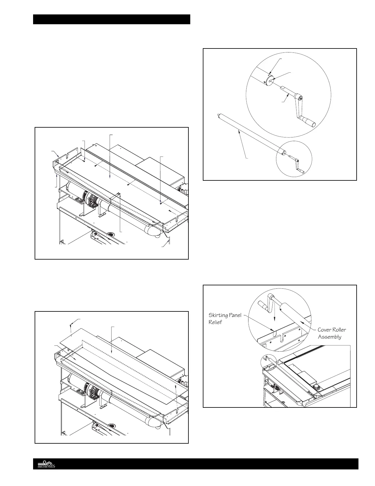
of the pool. To prepare for the coping installation, the drip tray,
cover roller, and coping attachments must be installed.
Position the drip tray above the plumbing assembly in between
each vertical support. Align the pre-drilled holes in the ends of
the drip tray with the corresponding holes in the vertical supports
and attach the drip tray using the 1" (25mm) truss head screws
located in the drip tray hardware bag. Align the pre-drilled holes
in the front bend of the drip tray with the corresponding holes in
the support beam and attach with the truss head screws. Secure
the back bend of the drip tray to the top ange of the pool wall
using the self-drilling screws located in the drip tray hardware
bag. Fig. 63.
Drip Tray
Self-Drilling
Screw
Truss Head
Screw
Truss Head
Screw
Support
Beam
Vertical
Support
Vertical
Support
Fig. 63
Position the UV cover into the drip tray. Align the holes in the
ends of the cover with the corresponding holes in the horizontal
face of the drip tray and attach the cover using the 1/2" (13mm)
truss head screws located in the drip tray hardware bag. Fig. 64
UV Cover
Truss Head
Screw
Drip Tray
Fig. 64
Align the cover system crank handle shaft with the square slot
located on the end of the PVC roller assembly. Insert the shaft
in the slot and tighten the set screw using a 1/8" (3mm) Hex
Wrench. Fig. 65.
Cover Roller
Assembly
Set screw
Square Slot
Crank Handle
Shaft
Fig. 65
e cover roller assembly ts into the “U” shaped notch of the
vertical support however, a notch will need to be cut out in the
skirting panel that will accommodate the crank handle. e
crank handle end of the roller should be installed on the side
of the pool with the most access. Determine which side of the
pool is most appropriate for opening the cover system. e side
skirting panel closest to the front of the pool has a pre-cut relief
on the backside of the panel which can be used as a template for
cutting out the notch for the roller assembly. Use a sharp utility
knife to score and cut out the notch in the skirting panel. Lower
the roller assembly into the notch of the vertical support and
skirting panel. Fig. 66.
Fig. 66
26