Liquiline CM442R/CM444R/CM448R
16 Endress+Hauser
Data logger function
• Adjustable scan time: 1 to 3600 s (1 h)
• Data logbooks:
– Max. 8 data logbooks
– 150,000 entries per logbook
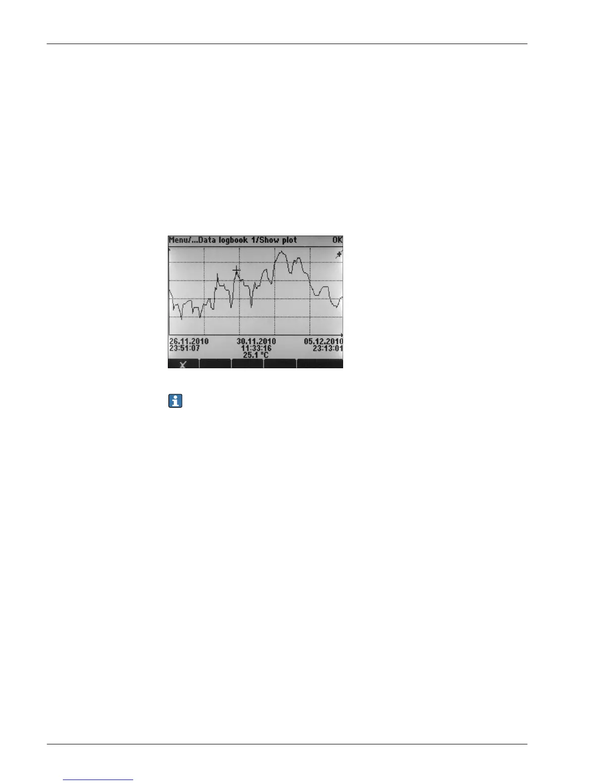
– Graphic display (load curves) or numerical list
• Calibration logbook: max. 75 entries
• Hardware version logbook:
– Hardware configuration and modifications
– Max. 125 entries
• Version logbook:
– E.g. software updates
– Max. 50 entries
• Operation logbook: max. 250 entries
• Diagnostics logbook: max. 250 entries
A0015032
11 Data logbook: Graphic display
Logbooks remain unchanged even after a software update.
SD card
The exchangeable storage medium enables:
• Quick and easy software updates and upgrades
• Data storage of internal device memory (e.g. logbooks)
• Transfer of complete configurations to a device with an identical setup (backup function)
• Transfer of configurations without the TAG and bus address to devices with an identical setup
(copy function)
• Saving of screenshots for documentation purposes
Endress+Hauser offers industry-approved SD cards as accessories. These memory cards provide
maximum data security and integrity.
Other SD cards can also be used. However, Endress+Hauser does not accept any responsibility for the
data security of such cards.
External signals for device control and for activating external devices
Hardware options, e.g. module "DIO" with 2 digital inputs and 2 digital outputs or fieldbus module
"485" enable the following:
• via a digital input signal
– measuring range switching for conductivity (upgrade code required, see accessories)
– switching between different calibration datasets in the case of optical sensors
– an external hold
– a cleaning interval to be triggered
– switching on and off a PID controller, e.g. via the proximity switch of the CCA250
– the use of the input as an "analog input" for pulse-frequency modulation (PFM)
• via a digital output signal
– the static transmission (similar to a relay) of diagnostic states, point level switch states etc.
– the dynamic transmission (comparable to a non-wearing "analog output") of PFM signals, e.g. to
control dosing pumps.




 To Next Page