Deltabar S FOUNDATION Fieldbus Commissioning
Endress+Hauser 27
Valves Meaning Preferred installation
1 Close 3.
P01-xMD7xxxx-11-xx-xx-xx-002
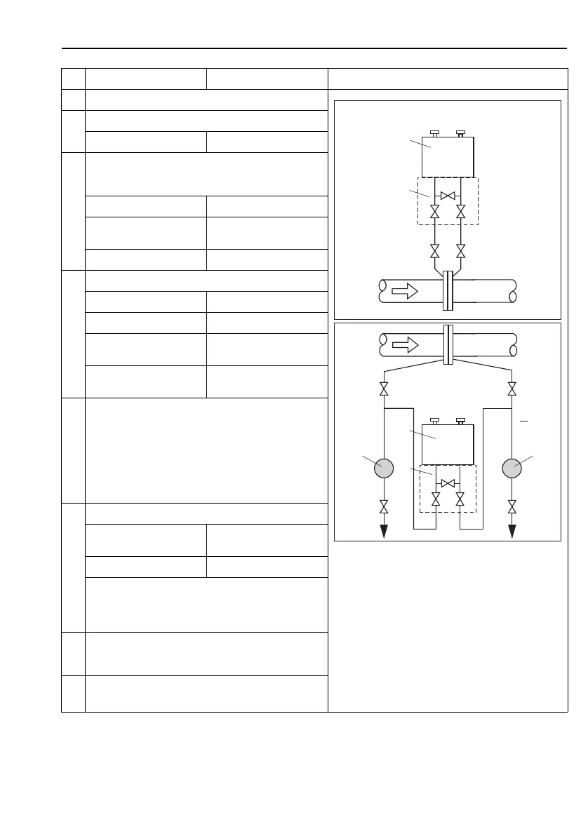
Fig. 9: Above: preferred installation for gases
Below: preferred installation for liquids
I Deltabar S, PMD70 or PMD75
II Three-valve manifold
III Separator
1, 5 Drain valves
2, 4 Inlet valves
3 Equalizing valve
6, 7 Vent valves on Deltabar S
A, B Shutoff valves
2 Fill measuring system with fluid.
Open A, B, 2, 4. Fluid flows in.
3 Clean impulse piping if necessary
1)
:
– by blowing out with compressed air in the case of gases
– by rinsing out in the case of liquids.
Close 2 and 4. Block off device.
Open 1 and 5.
Blow out/rinse out impulse
piping.
Close 1 and 5.
Close valves after cleaning.
4Vent device.
Open 2 and 4. Introduce fluid.
Close 4. Close negative side.
Open 3. Balance positive and negative
side.
Open 6 and 7 briefly, then
close them again.
Fill device completely with
fluid and remove air.
5 Carry out pos. zero adjustment if the following conditions are
met. If the conditions are not met, then do not carry out the
pos. zero adjustment until after step 6. See Page 29,
Section 6.4.3 and 25, Section 6.3.
Conditions:
– The process cannot be blocked off.
– The tapping points (A and B) are at the same geodetic
height.
6 Set measuring point in operation.
Close 3. Shut off positive side from
negative side.
Open 4. Connect negative side.
Now
–1
, 3, 5
, 6 and 7 are closed.
– 2 and 4 are open.
– A and B open (if present).
7 Carry out pos. zero adjustment if the flow can be blocked off.
In this case, step 5 is not applicable. See Page 29,
Section 6.4.3 and 25, Section 6.3.
8 Carry out calibration. See Page 28, Section 6.4.2.
1) for arrangement with 5 valves
I
II
+–
–+
6
6
7
7
–+
3
24
A B
A
B
+
1
5
24
3
II
I
IIIIII
 Loading...