Installation instructions TMT84
10 Endress+Hauser
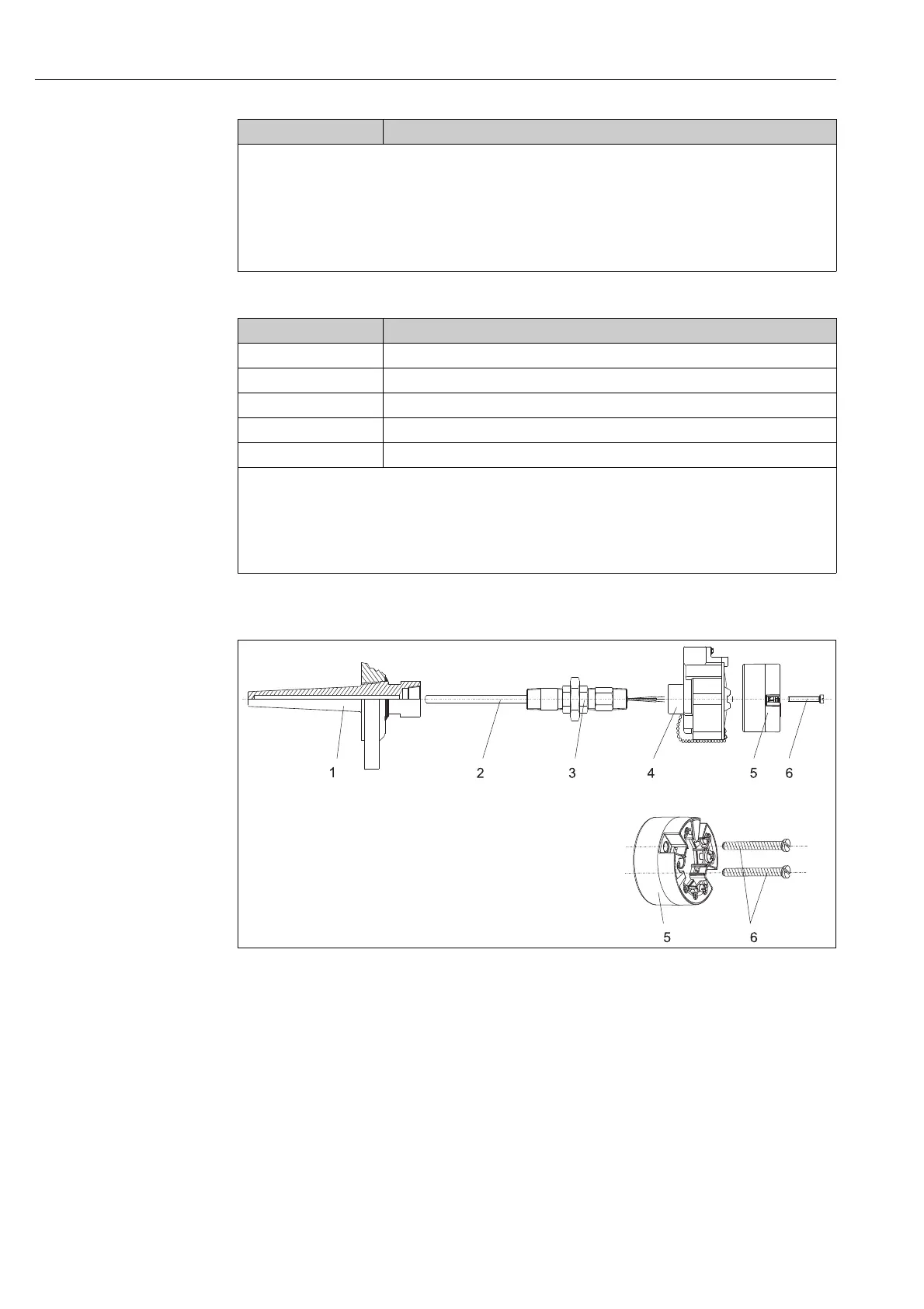
3.3.2 Mounting typical of North America
a0008520
Fig. 3: Head transmitter mounting
1 Thermowell
2 Insert
3: Adapter, threaded joint
4: Terminal head
5: Head transmitter
6: Mounting screws
Thermometer design with thermocouples or RTD sensors and head transmitter
• Fit the thermowell (1) on the process pipe or the container wall. Secure the thermowell according
to the instructions before the process pressure is applied.
• Fit the necessary neck tube nipples and adapter (3) on the thermowell.
• Make sure sealing rings are installed if such rings are needed for harsh environmental conditions
or special regulations.
Procedure:
1. Open the cover (1) of the field housing (5).
2. Fit the mounting springs onto the mounting screws (2) and guide them through the lateral bores of the head
transmitter (3). Then fix both mounting screws in position with the circlips (4).
3. Screw the head transmitter to the field housing.
4. When wiring is complete (see chapter 4), screw the field housing cover (1) back on.
Item C Mounting on DIN rail (DIN rail as per IEC 60715)
1 Mounting screws with springs
2 Head transmitter
3 Circlips
4 DIN rail clip
5DIN rail
Procedure:
1. Press the DIN rail clip (4) onto the top-hat rail (5) until it engages.
2. Fit the mounting springs onto the mounting screws (1) and guide them through the lateral bores of the head
transmitter (2). Then fix both mounting screws in position with the circlips (3).
3. Screw the head transmitter (2) to the DIN rail clip (4).
Item B Mounting in a field housing

 Loading...


