Wiring TMT84
14 Endress+Hauser
4.2 Connecting the sensor cables
Please refer to Fig. 5 for the terminal assignment of the sensor connections.
"
Caution!
When connecting 2 sensors ensure that there is no galvanic connection between the sensors (e.g.
caused by sensor elements that are not isolated from the thermowell). The resulting equalizing
currents distort the measurements considerably. The sensors must be galvanically isolated from one
another by connecting each sensor separately to a transmitter. The device provides sufficient
galvanic isolation (> 2 kV AC) between the input and output.
The following connection combinations are possible when both sensor inputs are assigned:
4.2.1 Connecting to spring terminals
a0008322
Fig. 6: Spring terminal connection
Procedure:
Sensor input 1
RTD or
resistance
transmitter,
two-wire
RTD or
resistance
transmitter,
three-wire
RTD or
resistance
transmitter,
four-wire
Thermocouple
(TC), voltage
transmitter
Sensor
input 2
RTD or resistance
transmitter, two-wire
-
RTD or resistance
transmitter, three-wire
-
RTD or resistance
transmitter, four-wire
----
Thermocouple (TC),
voltage transmitter
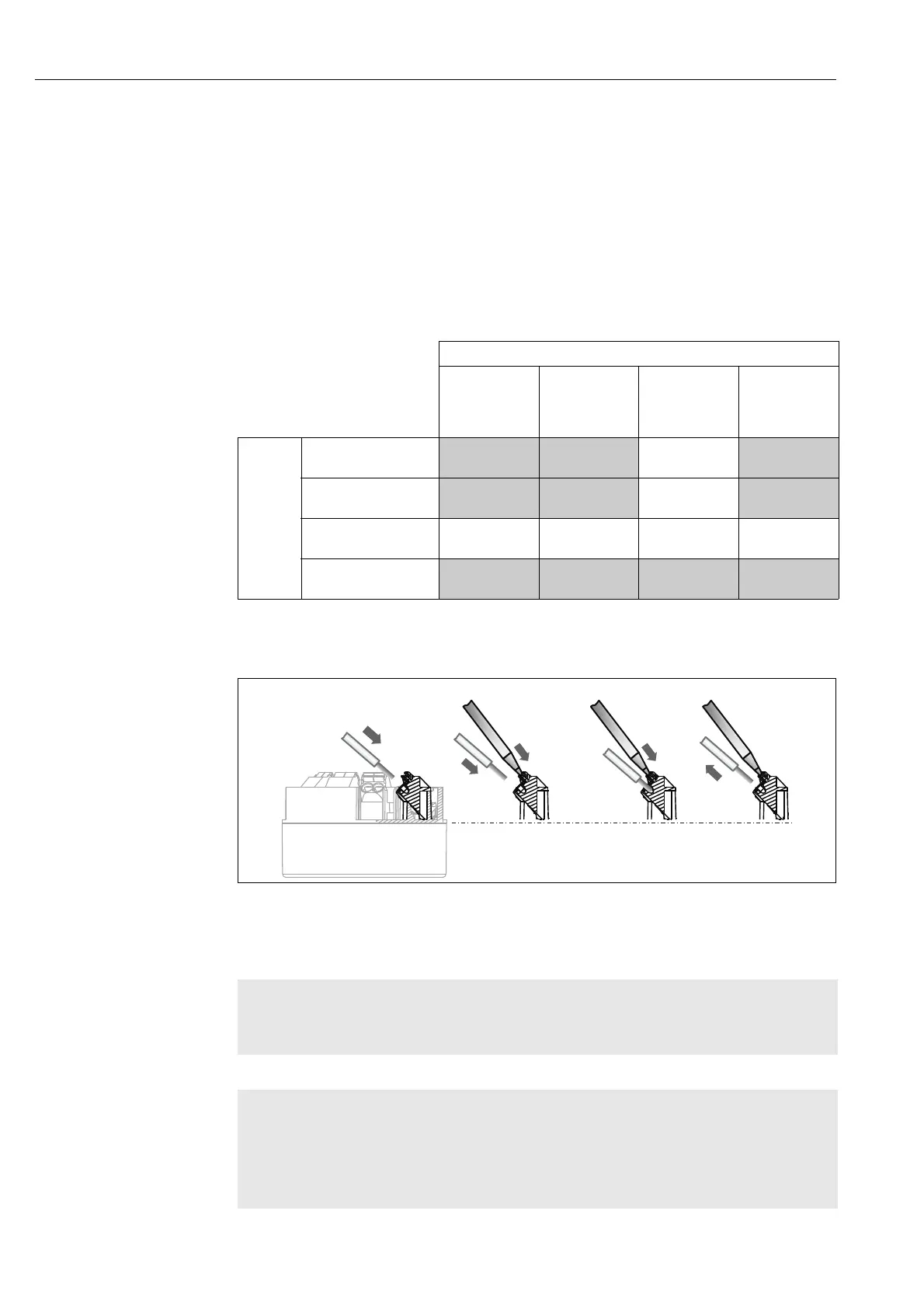
Item A, Solid wire: 1. Strip wire end. Minimum stripping length = min. 10 mm (0.39").
2. Insert the wire end into the terminal (A).
3. Check the connection by pulling on the wire lightly. Repeat from step 1 if
necessary.
Item B
Fine-strand wire without ferrule:
1. Strip wire end. Minimum stripping length = min. 10 mm (0.39").
2. Operate lever opener with tool (B).
3. Insert the wire end into the terminal (B).
4. Release lever opener.
5. Check the connection by pulling on the wire lightly. Repeat from step 1 if
necessary.

 Loading...


