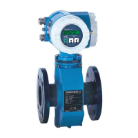
2.4 Design of the measuring system
(considering Promag 30 F as example)
Operation/Local display
Inside the housing of the transmitter there are miniature switches with which
altogether six operating parameters can be set (see page 37):
• Current range 0/4...20 mA
• Full-scale value scaling (volume/time), 8 steps
• Pulse weighting in decadic steps (volume), 8 steps
• Engineering units
• Function of the status output
Output of system/process errors
Flow direction recognition
• Creep suppression (on/off)
Using the Promag 30 local display, important parameters can be read off and
controlled at the measuring point directly:
• Flow rate and/or totaliser value
• Technical units (SI/US units)
• Process variables (e.g. creep rate, partial pipe filling)
• Error messages
Using the three operating keys, it is also possible to select and activate various
functions. A small pin is used to press the keys down (keep pressed for
approx. 0.5...0.8 s).
Power supply*
85...260 V AC 45...65 Hz
20... 55 V AC
16... 62 V DC
Cable entry
Sensor
Measuring
electrodes
Reference electrode
Screw cover of electronic
compartment (6 parameters can
be set here with internal miniature
switches)
Option: local display
Screw cover
Terminal compartment
ba008y04
Empty pipe
detection electrode
Outputs*
Current output active
galvanically separated
0/4...20 mA
R
L
≤
700
Ω
Pulse output Open Collector, passive
galvanically separated
0...400 Hz
Status output Open Collector, passive
galvanically separated
configurable for:
•
output of system or process errors
•
detection of the direction of flow
Auxiliary input The auxiliary voltage to be applied
to activate the function is in the
region of 3...30 V DC
•
Measured value suppression
•
Totalizer reset (with local display only)
* Technical data: see Chapter 7
Fig. 4
2. System Description Promag 30
10 Endress+Hauser
 Loading...