Do you have a question about the Endress+Hauser PROMAG 33 and is the answer not in the manual?
Guidance on safe and reliable operation of the measuring instrument.
Instructions for physical installation and electrical wiring.
Steps to follow for initial setup and operation.
Defines the intended applications and limitations of the Promag 33.
Highlights potential hazards and important information for safe operation.
Specifies qualifications and responsibilities for personnel.
Procedures for returning instruments and handling hazardous materials.
Recommendations and avoidance of locations for optimal measurement.
Guidance on vertical and horizontal mounting positions.
Ensuring IP 67 protection after installation and servicing.
Step-by-step guide for connecting the transmitter.
Instructions for connecting sensor and transmitter cables remotely.
Ensuring equal electrical potential between sensor and fluid.
Checks and procedures before and during system start-up.
Overview of the LC display and control buttons.
Navigating and using the E+H operating matrix.
Configuring and measuring using the HART protocol.
Configuration of the current output signal.
Configuration of pulse and frequency outputs.
Configuration of relay functions and switching points.
Functions for controlling single or two-stage batching cycles.
Configuration of communication interfaces like HART and RS 485.
Settings for low flow cutoff, noise suppression, and empty pipe detection.
Describes system and process error responses for outputs.
Guides for identifying and resolving common errors.
Lists all error, alarm, and status messages with causes and remedies.
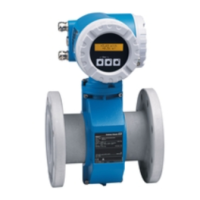
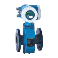
| Device Type | Electromagnetic flowmeter |
|---|---|
| Housing Material | Aluminum, stainless steel |
| Measured Medium | Conductive liquids |
| Measuring Principle | Electromagnetic induction |
| Process Pressure | Max. 40 bar (580 psi) |
| Output Signal | 4 to 20 mA HART, pulse/frequency/switch output |
| Communication | HART |
| Power Supply | 24 V DC |
| Degree of Protection | IP67 |
| Liner Materials | PTFE, PFA |
| Electrode Materials | Hastelloy |
| Measured Variable | Volume flow, flow velocity |
| Minimum Conductivity | ≥5 μS/cm |
| Accuracy | ±0.2% of measured value ±1 mm/s |