Prosonic S FDU90/91/91F/92/93/95/96
10 Endress + Hauser
Installation conditions
Installation options
(Examples)
L00-FDU9xxxx-17-00-00-xx-001
A: at girder or angle bracket; B: with alignment unit FAU40; in ATEX Zone 20 the alignment unit can be used for zone
separation; C: with a 1" sleeve welded to a grating
L00-FDU9xxxx-17-00-00-xx-007
A: Installation with cantilever and wall bracket; B: Installation with cantilever and mounting frame; C: The cantilever can
be turned in order to position the sensor over the centre of the flume.
Cantilever, wall bracket and mounting frame are available as accessories (see chapter "Accessories").
"
Caution!
The cable of the sensors is not designed as a supporting cable. Do not use it as a suspension wire.
"
Caution!
The sensor membrane is part of the measuring system and must not be damaged during installation.
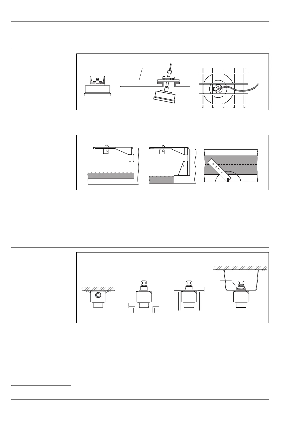
Mounting versions
L00-FDU90xxxx-17-00-00-xx-001
A: FDU90: Ceiling mounting
B: FDU90: Mounted at front thread (G1-1/2 or NPT1-1/2)
C: FDU9x: Mounted at rear thread (G1 or NPT1)
D: FDU90, FDU91, FDU91F, FDU92: Mounting with G1 counter nut
1)
; 42AF
ABC
Zone 20
-
Zone 21
-
.
FAU40
A
B
C
FDU9x FDU9x
ABC D
FDU90
FDU9x
FDU90
FDU9x
SW41
41AF
1) The counter nut with gasket is supplied for the sensors FDU90, FDU91, FDU91F and FDU92 with a metric thread G1 at the process connection.
 Loading...