Prosonic S FDU90/91/91F/92/93/95/96
Endress + Hauser 7
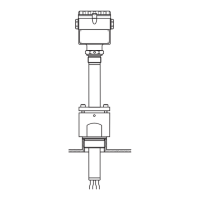
Electrical connection
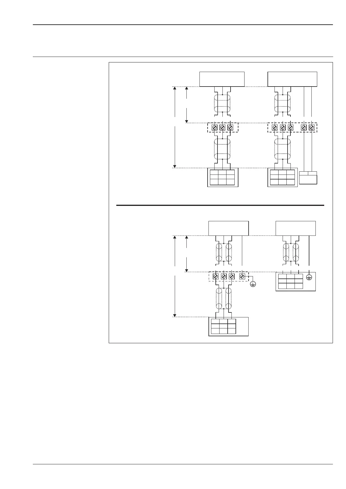
Connection diagram
L00-FDU9xxxx-04-00-00-xx-002
(A): without sensor heater;
(B): with sensor heater;
(C): grounding at the terminal box;
(D): grounding at the transmitter FMU90;
(1): Screen of the sensor cable;
(2): Terminal box;
(3): Screen of the extension cable;
Colours of the strands: YE = yellow; BK = black; RD = red; BU = blue; BN = brown; GNYE = green-yellow
YE
9
(12)
BK
10
(13)
RD
11
(14)
FDU90/91/92
(FDU80/80F/81/81F/82)
BK
YE
RD
(1)
YE
9
(12)
BK
10
(13)
RD
11
(14)
FDU91F/93/95/96
(FDU83/84/85/86)
BK
YE
RD
GNYE
(2)
(3)
FMU90
(1)
(2)
(3)
FMU90
YE
9
(12)
BK
10
(13)
RD
11
(14)
FDU90/91
(FDU80/81)
BK
YE
RD
(1)
(2)
(3)
FMU90
BN BU
24VDC
+
-
(A) (B)
(C)
max.
300 m
YE
9
(12)
BK
10
(13)
RD
11
(14)
FDU91F/93/95/96
(FDU83/84/85/86)
BK
YE
RD
GNYE
(1)
FMU90
(D)
max.
30 m
max.
300 m
max.
30 m
FDU90/91/92
(FDU80/80F/81/81F/82)
FDU91F/93/95/96
(FDU83/84/85/86)
 Loading...