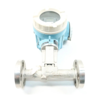
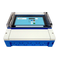
Prothermo NMT81 Installation
Endress+Hauser 25
5.10.1 NMT81 Installation
Confirm that the size of the nozzle and the flange is matched prior to mounting NMT81 on
the tank. The flange size and the rating of NMT81 vary depending on the customer’s
specifications.
• Check the flange size of NMT81.
• Mount the flange on the top of the tank. The deviation of the flange from the horizontal
plane should not exceed +/- 1 degree.
• Install NMT81 at least 300 mm (11.81 in) or API 7: 1 000 mm (39.4 in) away from the
wall. This will ensure that the temperature measurement is not affected by the tank's
ambient or wall temperature.
A0026889
17 Allowable inclination of mounting flange
1 Nozzle
Insert the temperature probe and the optional WB probe and low profile anchor weight
through the tank nozzle at the top of the tank.
To prevent damage to the temperature probe and WB probe, ensure that they do not
touch anything during insertion through the installation nozzle.
For NMT81 installation, there are three types of flange adjusters as follows.
A0045255
18 flanges
A Thread type adjuster
B Non-height adjuster
C Height adjuster
1 Adjuster
2 NMT81 flange
3 Tank top flange (prepared by a customer)
Non-height adjuster type of NMT81
Make sure to align the correct orientation position of the device prior to tightening bolts.
 Loading...

