Modbus Integrator's Guide for the Cordex® CXC HP Controller | 3 - Using Modbus
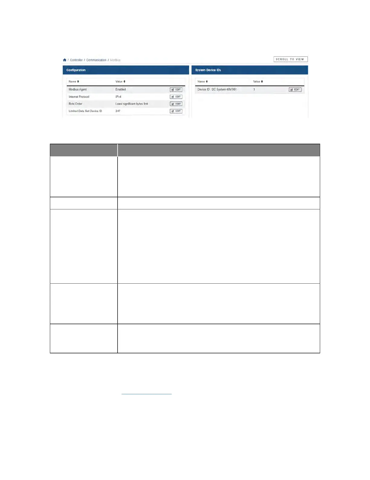
Figure 3-1 Enabling the Modbus agent
Table 3-1 Configuration
Name Description
Modbus Agent Enables or disables Modbus service. When enabled, the service is initialized and
the controller is ready to accept requests. The controller serves data for both the
limited and full data set.
The default value is Disabled.
Internet Protocol The Internet Protocol IPv4 or IPv6 to be used for communication.
Byte Order Changes the byte order of 32-bit data. This setting is used to change whether the
most or least significant byte comes first. This setting should be set according
to the requirements of the Modbus client. The client will decode and format data
needed to understand the correct byte order. The default value is Least signifi-
cant bytes first.
Reverse the bytes for the input values registers (function code 4). These values
are stored as 32-bit floating point and occupy 2 registers each. By default the val-
ues are stored with least significant bytes first (little endian).
Limited Data Set ID This ID is a small set of DC system data. See the Modbus reference section for
the data mapping. The default is 247, the range is 241 to 250.
The data available through this device ID provides a limited view of the DC system
information.
Device ID This table has a device ID for each supported system. Device IDs are automatical-
ly assigned when systems are created. The devices IDs must be unique. See the
Modbus reference section for the data mapping. The range is 1 to 240.
Client application setup
Client applications connect to the controller through TCP/IP via a Modbus client. The standard Modbus
service port 502 is used. The sample application used for the following figure, is Modscan32 available at
WinTECH Software Design www.win-tech.com.
0350114-J0 Rev N Page 9
 Loading...