16
www.enersys.com
Publication No. US-MP-OM-001
March 2017
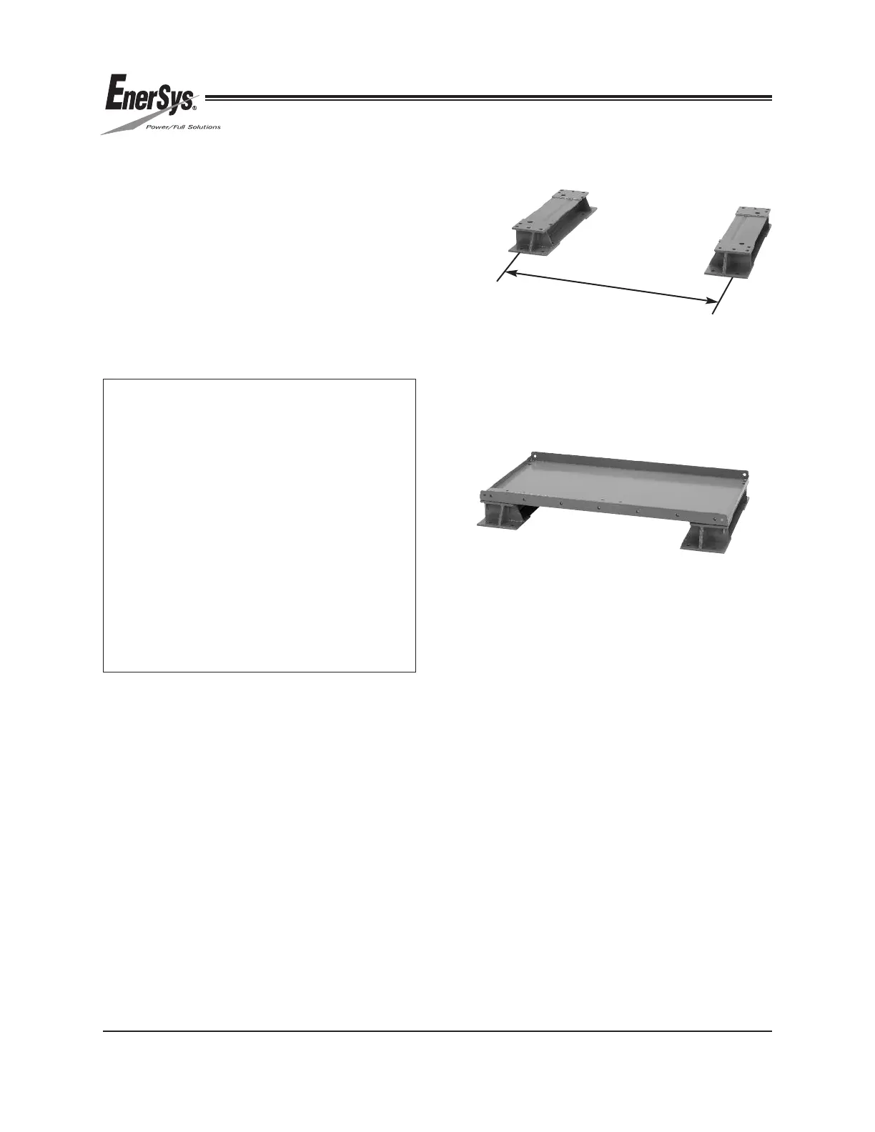
1. Use the system base beams to layout
the system configuration.
2. Refer to Figure 1 and Table 7.1 to
determine the anchor spacing. The
top module weldment can also be used
to position the base beams, loosely
bolt the top module weldment to the base
beams. See Figure 2.
3. Mark the floor with the location of the floor
anchors. All holes are to be used when
anchoring to the floor. Dimension “L” in
Figure 1 is to the outermost set of holes.
FIGURE 1
L
FIGURE 2
7.0 SYSTEM LAYOUT
Before installing the battery system, layout
available floor space including aisles for
installation, maintenance and possible cell
replacement. Review the installation
considerations of this manual (Section 5.0).
The recommended clearance between
these racks and any objects (including walls
and equipment) is 4 inches (102 mm).
NOTE:
• Floor anchoring is REQUIRED for all
installations.
• Floor anchors are not provided.
• Allow sufficient clearance between
adjacent walls or equipment for proper
installation of anchors. Please check your
local codes for clearances required.
• Floor anchor design (including, but not
limited to size, quantity, and capacity)
and installation are the responsibility of
the user/installer — based on applicable
codes and regulations.
• Follow the user’s design and the
manufacturer’s instructions.
 Loading...