23
www.enersys.com
Publication No. US-MP-OM-001
March 2017
11.0 ELECTRICAL BONDING
INSTRUCTIONS
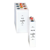
For each cell module, install (1) M6 self-tapping
screw through front lip of the cell module into the
frame module weldment. See Figure 14 & 14a.
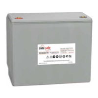
For each module to base, module to module and
top to module joint install (2) M6 self-tapping
screws (1 per side). See Figure 14b.
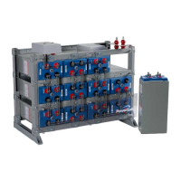
12.0 TERMINAL PLATES
Terminal plates are provided with the battery
system to provide a system connections point.
All system connections must be made to the
terminal plate and NEVER to the cell terminal.
Top termination is standard, side termination is
optional.
1.
Clean the terminal plate electrical contact
areas with a stiff-bristle nonmetallic
brush/pad until the surface is bright.
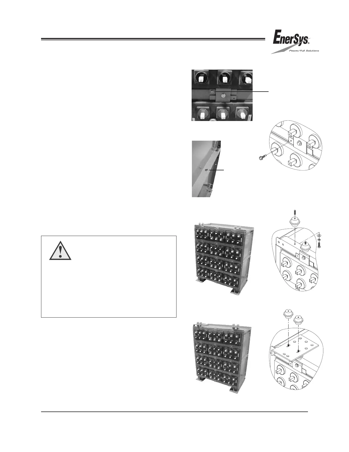
2. Assemble and install the terminal plate
assembly finger-tight as shown in
Figure 15, 15a, 16 & 16a.
3. Torque all bolts to 15 ft-lbs. Hand tighten red
insulators (cherries).
FIGURE 15
FIGURE 15a
FIGURE 16a
FIGURE 16
FIGURE 14
FIGURE 14b
Self-Tapping
Screw
FIGURE 14a
CAUTION
Tin plated parts do not require plating removal
to provide an adequate contact surface, only
foreign material removal. Very light brushing and
cleaning with a cloth is generally sufficient.
Lead Plated Parts — Be careful not to remove
the lead plating with excessive brushing
Self-Tapping
Screw
 Loading...