20
www.enersys.com
Publication No. US-MP-OM-001
March 2017
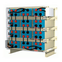
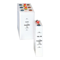
FIGURE 6
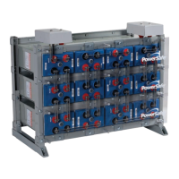
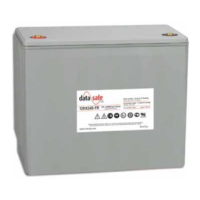
FIGURE 7
FIGURE 7b
5.
Place the FIRST PowerSafe
®
mP Series cell
module onto the LOWEST EMPTY shelf, with
the terminals toward the front.
Refer to the
Assembly Drawing for the cell polarity
configuration.
6. Slide the cell module back into a safe position.
Remove the shipping retainer.
7. Slide cell module completely into position so the
lip of the cell module touches the front of the
shelf.
8. Place another cell module onto the shelf next to
the previously placed cell module. Refer to
the Assembly Drawing for the cell polarity
configuration. See Figure 6.
9. Leave safety caps on terminals until connections
are ready to be made.
9.1 Module Retainers
1. For each cell module, install retainer plates,
using a M10x1.5 - 25mm Serrated Hex Bolt.
See Figure 7. The middle rows use a flat retainer,
the top and bottom rows use a retainer with a
formed edge. See Figure 7a & 7b.
2. Torque to 20 ft-lbs.
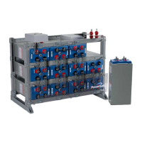
3. Install cell modules and retainer plates as
described until module is full. See Figure 7.
CAUTION
The larger cell modules are too heavy to manually
lift on to the shelves. To avoid personal injury use
the appropriate lifting devices when lifting
modules onto the shelves.
FIGURE 7a
 Loading...