24
www.enersys.com
Publication No. US-MP-OM-001
March 2017
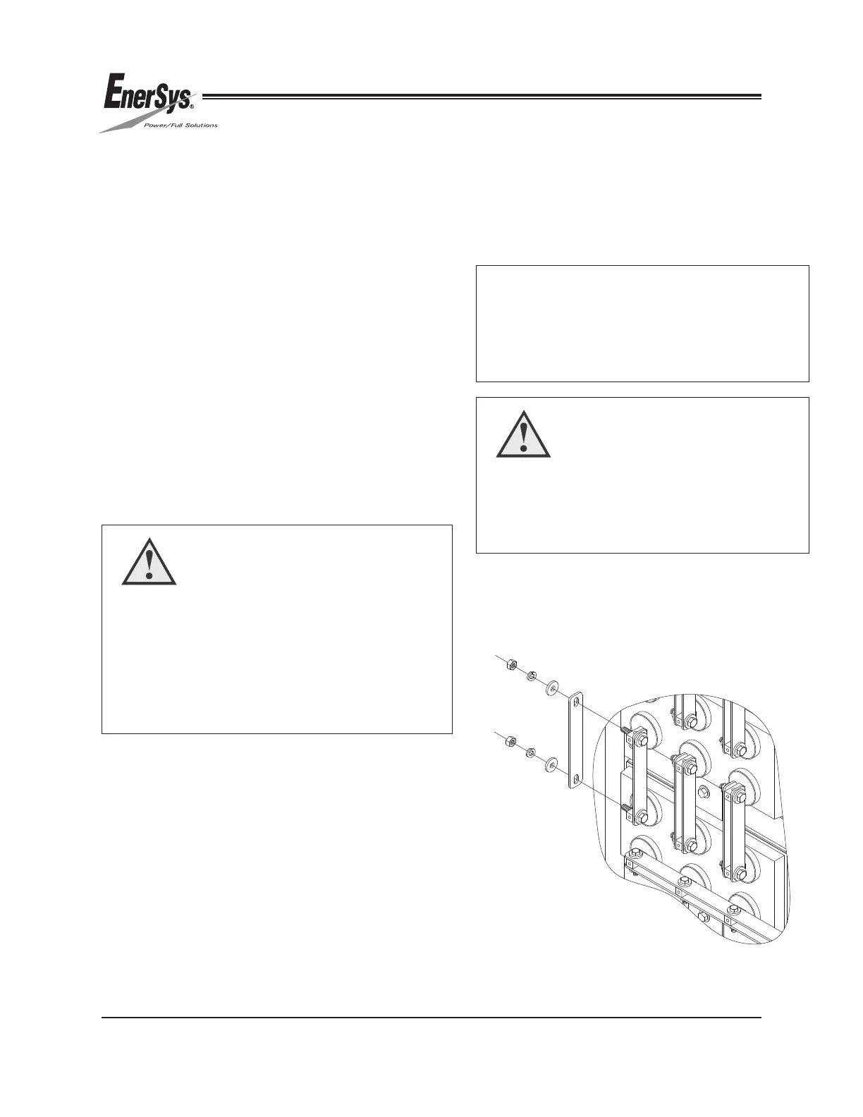
FIGURE 17
13.0 CONNECTIONS
The system is now ready to be connected.
The cells must be connected according to the
polarities on the and the
following instructions.
13.1 Inter-Cell Connectors
The connections are made by bolting the supplied
lead or tin-plated copper inter-cell and inter-module
connectors to the cell terminals of opposite polarity
on adjacent cells. See for
details.
1. Clean the contact surface of the inter-cell
connector using a stiff-bristle nonmetallic
brush/pad.
2. Apply a light coat of NO-OX-ID grease to the
contact surfaces of the inter-cell connector and
terminal post.
a. Hex Bolt
b. Flat Washer
c. Inter-cell Connector
d. Battery Terminal
e. Inter-cell Connector
f. Flat Washer
g. Lock Washer
h. Hex Nut
3. Bolt all inter-cell connectors according to
the . Assemble as
the example shown in Figure 17 and
below list:
CAUTION
Tin plated parts do not require plating removal to
provide an adequate contact surface, only foreign
material removal. Very light brushing and cleaning
with a cloth is generally sufficient.
Lead Plated Parts — Be careful not to remove the
lead plating with excessive brushing.
WARNING
Stamped flat washers may have one sharp
edge. Install the washer with the sharp edge
away from the inter-cell connector to avoid
damaging the plating.
NOTE:
Inter-cell connections vary in length depending
on the type of connection (cell-to-cell, module-
to-module, etc.). Always insure that there is a
connector bar on each side of the terminal.
 Loading...