18
www.enersys.com
Publication No. US-MP-OM-001
March 2017
8.0 FRAME ASSEMBLY AND
INSTALLATION
To assemble and install the frame for the
PowerSafe
®
mP Series battery system, follow
the procedure below using the system layout
determined in the “System Layout” section of
this manual (Section 7.0). This manual uses a
3 wide x 4 high system for reference purposes.
8.1 Base Beams
1. LEVEL with customer-supplied floor shims,
and anchor in place. Do NOT torque
anchor bolts until frame assembly is
complete.
2. Install ALL base beams before continuing.
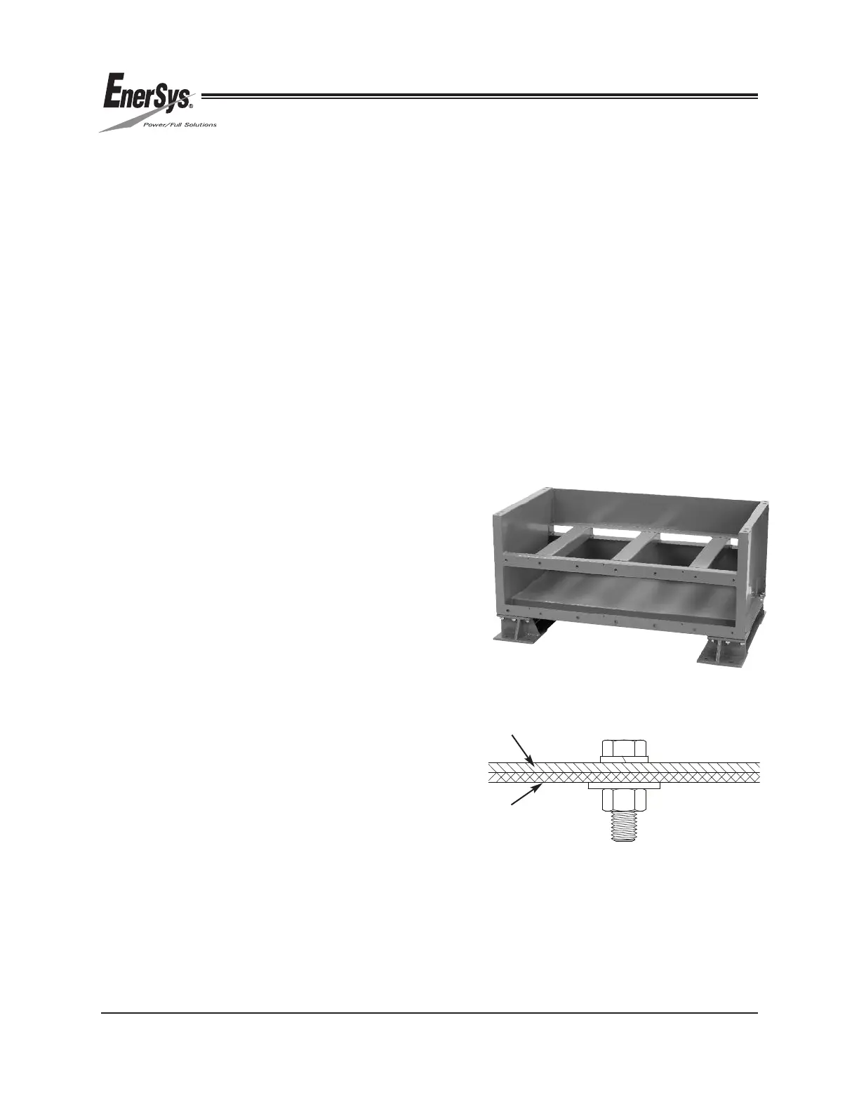
8.2 Frame Module Weldment
1. Install frame module weldment on top of
base beams. See Figure 5.
2. Bolt frame module weldment to base beams.
Refer to below list for hardware order and
Figure 5a:
• Hex Bolt (M12x1.75-40mm)
• Lock Washer
• Frame Module Weldment
• Base Beam
• Flat Washer
• Hex Nut
3. Torque all module connections (except anchor
bolts) to 75 ft-lbs.
!!'"- #'(!!(( '( "$&(#,(
&""$)!+!"#("-'(#($(
%&* $)'!- #'(!!"$)! '"#)!+ !!
$!!$+("($$ #'(!! #!!'#,(
FIGURE 5a
Frame Module Weldment
Base Beam
FIGURE 5
 Loading...