11
necessario seguire con scrupolo le indicazioni
descritte in questo manuale.
Spostamenti: prima di qualsiasi spostamento è
necessario controllare la presenza e l'integrità di tutti
i dispositivi sicurezza e di protezione. Se soltanto uno
di fosse mancante o non integro, è vietato sia il
trasporto che il successivo utilizzo dell’attrezzatura.
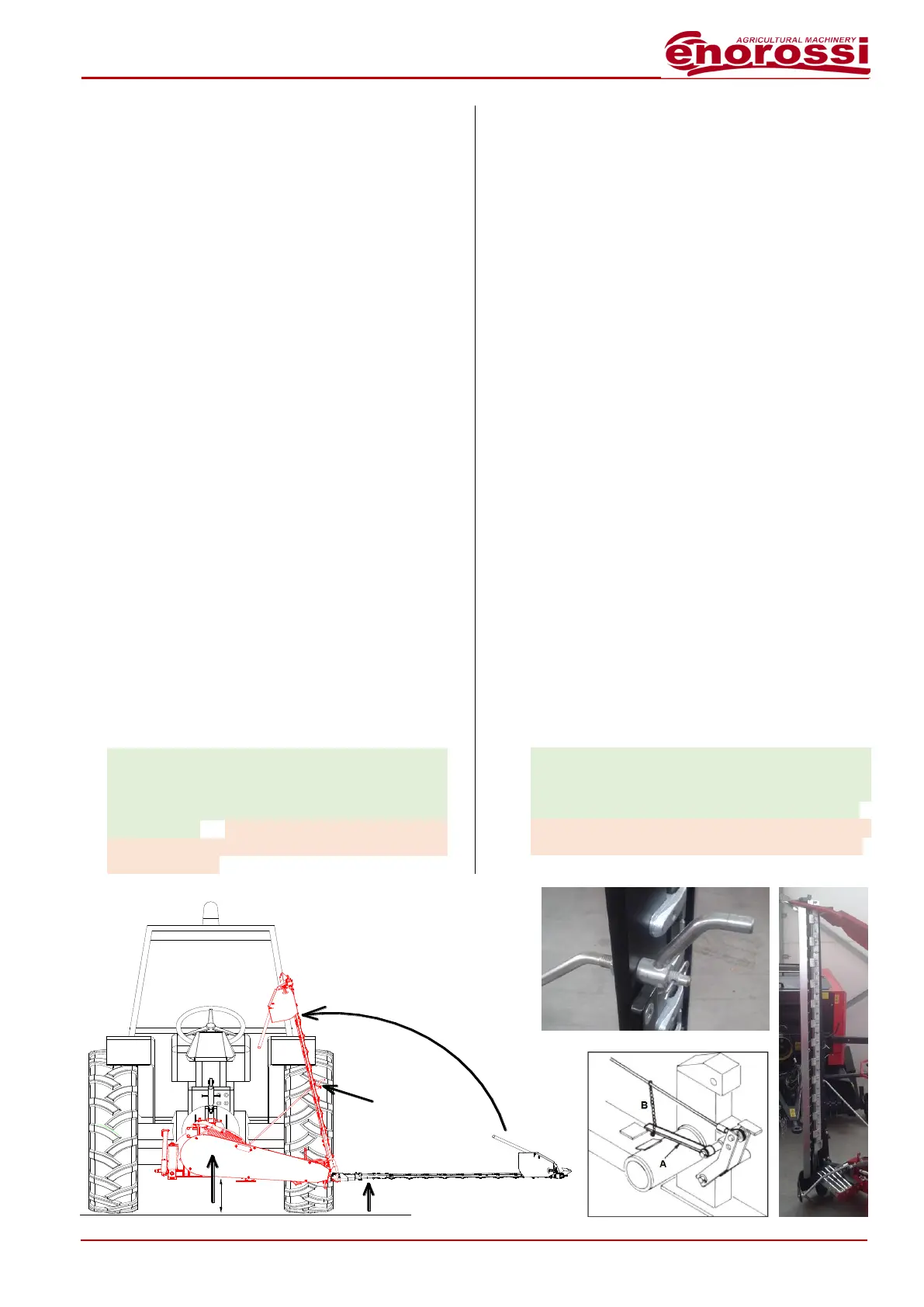
Per qualsiasi spostamento la barra falciante deve
sempre essere disposta in CONFIGURAZIONE DA
TRASPORTO, mostrata in fig.3, ossia con
l’attrezzatura sollevata da terra (3), la barra coltelli
ruotata verso l’alto di oltre 90° (2) ed il gancio di
sicurezza inserito. Tale configurazione è necessaria
per garantire all’attrezzatura di essere contenuta,
rispetto all’asse di simmetria longitudinale del
trattore, nei limiti di sporgenza laterale consentiti dal
codice della strada.
Prima di fare assumere alla barra falciante la
configurazione da trasporto, allontanare tutte le
persone che si possono trovare nella zona di ma-
novra. Dopodiché, eseguire le seguenti operazioni:
se l’intervento viene effettuato dopo l’installazione
della barra falciante allora è necessario avviare il
trattore e passare al punto due. Se, invece,
l’intervento viene effettuato al termine del lavoro,
allora sarà necessario disinserire la presa di forza
lasciando acceso il motore del trattore;
1. utilizzando il sollevatore idraulico del trattore,
sollevare l’intera attrezzatura di circa 15 ÷ 20 cm.
dal suolo (1 - fig.3);
2. modelli meccanici: sollevare manualmente la
barra di taglio (2 - fig.3) e contemporaneamente
anche il fermo meccanico (A) dopo averlo fissato
al cavo di sollevamento tramite l’apposita
catenella (B) - modelli idraulici: sollevare la
barra di taglio manovrando in cabina la rispettiva
leva di comando;
described in this manual must be meticulously
performed.
Movements: before moving, it is necessary to verify
that all safety and locking devices are present and
integral. If one was missing or not integral, it is
forbidden both the transport and the use of the
equipment.
For every movement the disc mower must be always
disposed in the TRANSPORT CONFIGURATION,
shown in fig.3, that is with the equipment lifted of
about (3) from the ground, the blade bar rotates
upwards more than 90° (2) and the safety hook
engaged. Such configuration is necessary to permit
to the equipment to be contained within the side
projection limits, regarding to the longitudinal axle of
symmetry of the tractor, allowed from Highway Code.
Before moving the mower into transport position,
send away all persons who may be in the
manoeuvring area. To position for road transport or
for moving from one field to another, carry out the
following operations:
if the intervention is performed after the mower
installation then it is necessary start the tractor and
pass to point two. If the intervention is performed to
the end of the work then it is necessary disengage
the power take off and leaving the tractor engine on;
1. lift the equipment of about 15 ÷ 20 cm from the
ground, by using the tractor hydraulic lift (1 -
fig.3);
2. mechanical models: to manually lift the cutting
bar (2 - fig.3) and contemporary also the
mechanical stop (A) after having fixed it to the
lifting cable by means of the special chain (B) -
hydraulic models: to lift the cutting bar by
handling in the cabin the respective control lever;
Fig.3
TIRANTE DI AGGANCIO / HOOKING TIE ROD