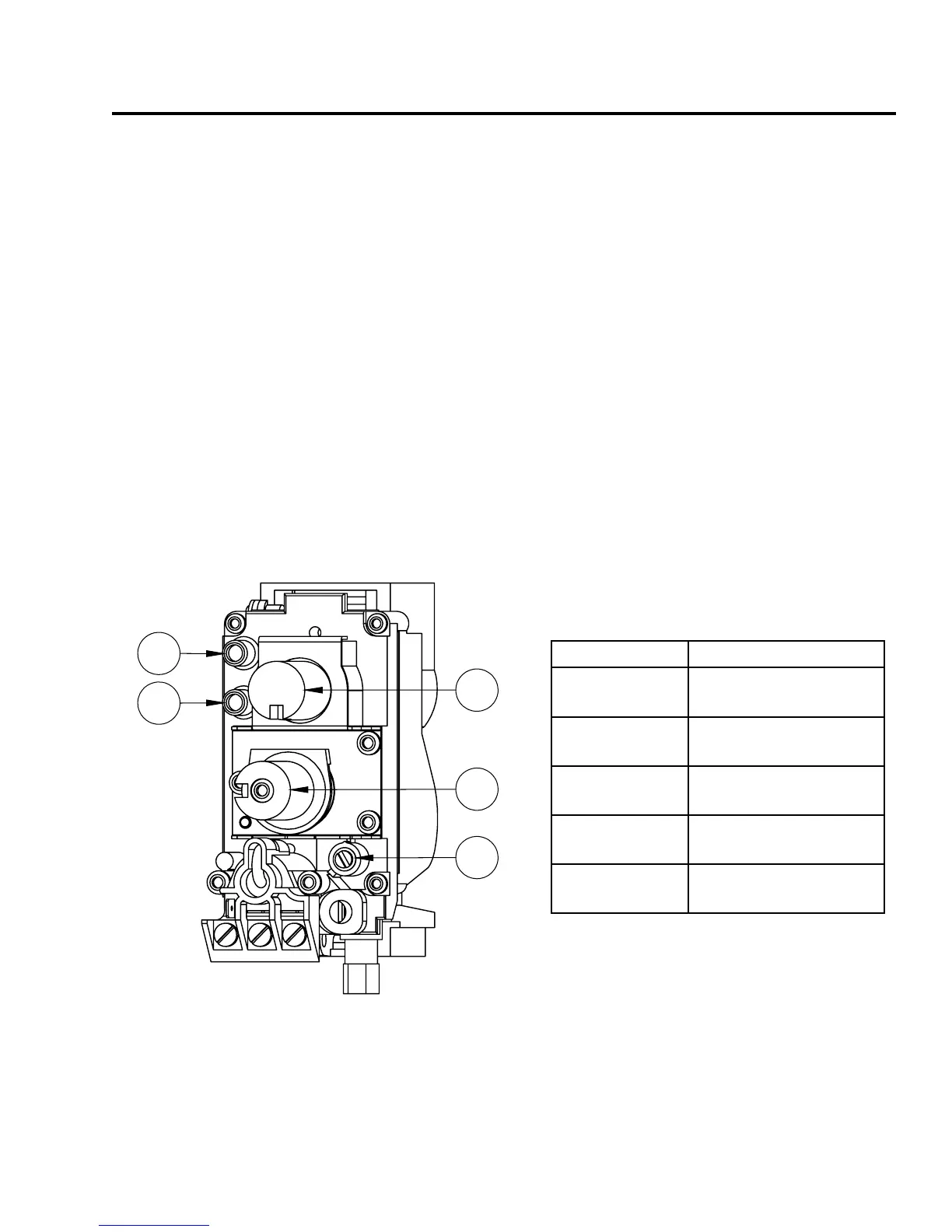
TO TEST VALVE PRESSURES (INPUT RATES):
The pressure taps are located on the front side of the valve (see Figure 27).
1. Remove valve control knobs.
2. Using a long at bladed screwdriver, turn set screw one (1) turn counter-clockwise to loosen.
3. Place
5
/16 in (8 mm) I.D. hose over the pressure taps.
4. Check pressures using a manometer.
5. When nished, remove hose and tighten set screw.
6. Re-install the knobs. Pointer on knobs can be removed and oriented correctly to point at the right
location.
Always check for gas leaks with a soap and water solution after completing the required
pressure test.
NEVER USE AN OPEN FLAME FOR LEAK TESTING.
23
Initial Installation
QUALIFIED INSTALLERS ONLY
1
2
3
4
5
Item number DescrIptIon
1 Control Knob
(On/Off/Pilot)
2 Gas Flow Adjustment
Knob
3 Pilot Adjustment
Screw
4 Inlet Pressure Test
Point
5 Outlet Pressure Test
Point
Figure 27: Valve Details.
Table 6: Valve Details.