2.3 Wire size
The wiring and installation methods must conform to the national and local electrical code
requirements.
PV wire size
The PV array's output current varies with its size, connection method, and sunlight angle.
The minimum wire size can be calculated by its ISC(short circuit current). Please refer to
the ISC value in the PV module's specifications. When the PV modules are connected in
series, the total ISC is equal to any PV module's ISC. When the PV modules are connected
in parallel, the total ISC is equal to the sum of all the PV module's ISC. The PV array's ISC
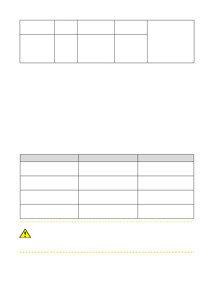
must not exceed the controller's maximum PV input current. For max. PV input current and
max. PV wire size, please refer to the table as below:
When the PV modules are connected in series, the total voltage must not exceed
the max. PV open circuit voltage
(Tracer**10AN)/138V(Tracer**15AN)/180V(Tracer**20AN)at 25 environment
temperature.
Battery wire size
The battery wire size must conform to the rated current, the reference size as below:
 Loading...